Drawing
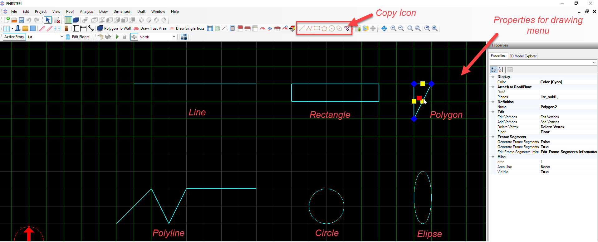
In this chapter the users will be able to draw and design the main elements which software dose like (Walls, Single Truss, Truss Area, Roof, ceiling). As well as another geometry shapes like circles, polygons, etc.
Note: To draw any element in ENRSTEEL there is 3 ways:
- Click on the icon which represent the function directly from Toolbars.
- From menu bar go to draw tab then select what you want to draw.
- Write the shortcut for what you want to draw in the modeling area then hit enter or right-click on the mouse. See the shortcuts abbreviation at the end of this guide.
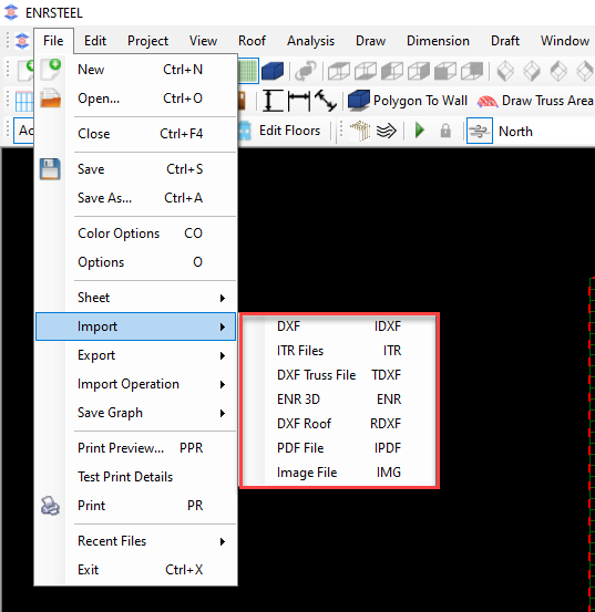
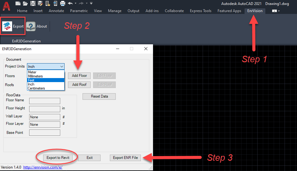
Note: Users can import DXF, PDF or image files and start layout them walls and trusses according to that DXF, PDF, or image. Or they can draw walls, trusses on AutoCAD and import it as ENR 3D. the fig below explain how it works by steps.
Note: To import files from AutoCAD you have to install special tool from ENRvision. Users can export files from AutoCAD to Rivet and add them sections if they have a library there. Any file drawn in ENRSTEEL can be exported to AutoCAD or Rivet.
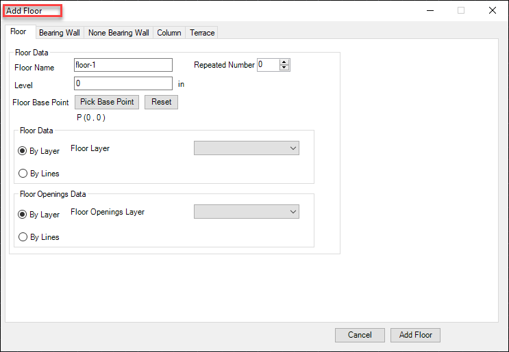
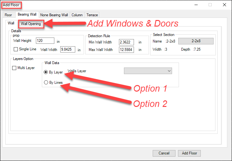
Users have 2 options to insert walls, roof, windows and doors . If they drew it by separate layers in AutoCAD they can use (Option 1) if not they have to drew lines at elements borders and use (Option 2).Users have 2 options to insert walls, roof, windows and doors . If they drew it by separate layers in AutoCAD they can use (Option 1) if not they have to drew lines at elements borders and use (Option 2).
Walls
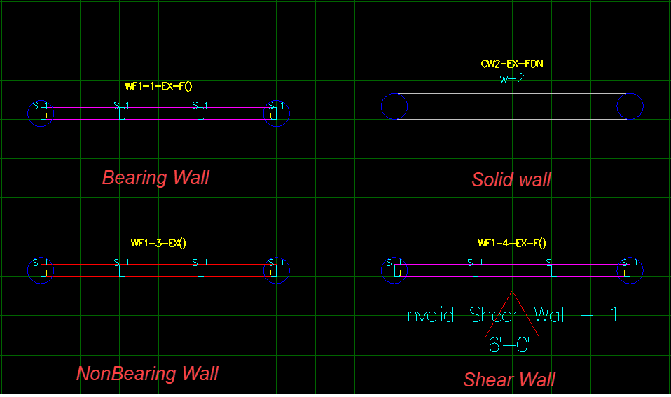
ENRSTEEL gives users the availability to draw and design 4 types of walls as the following:
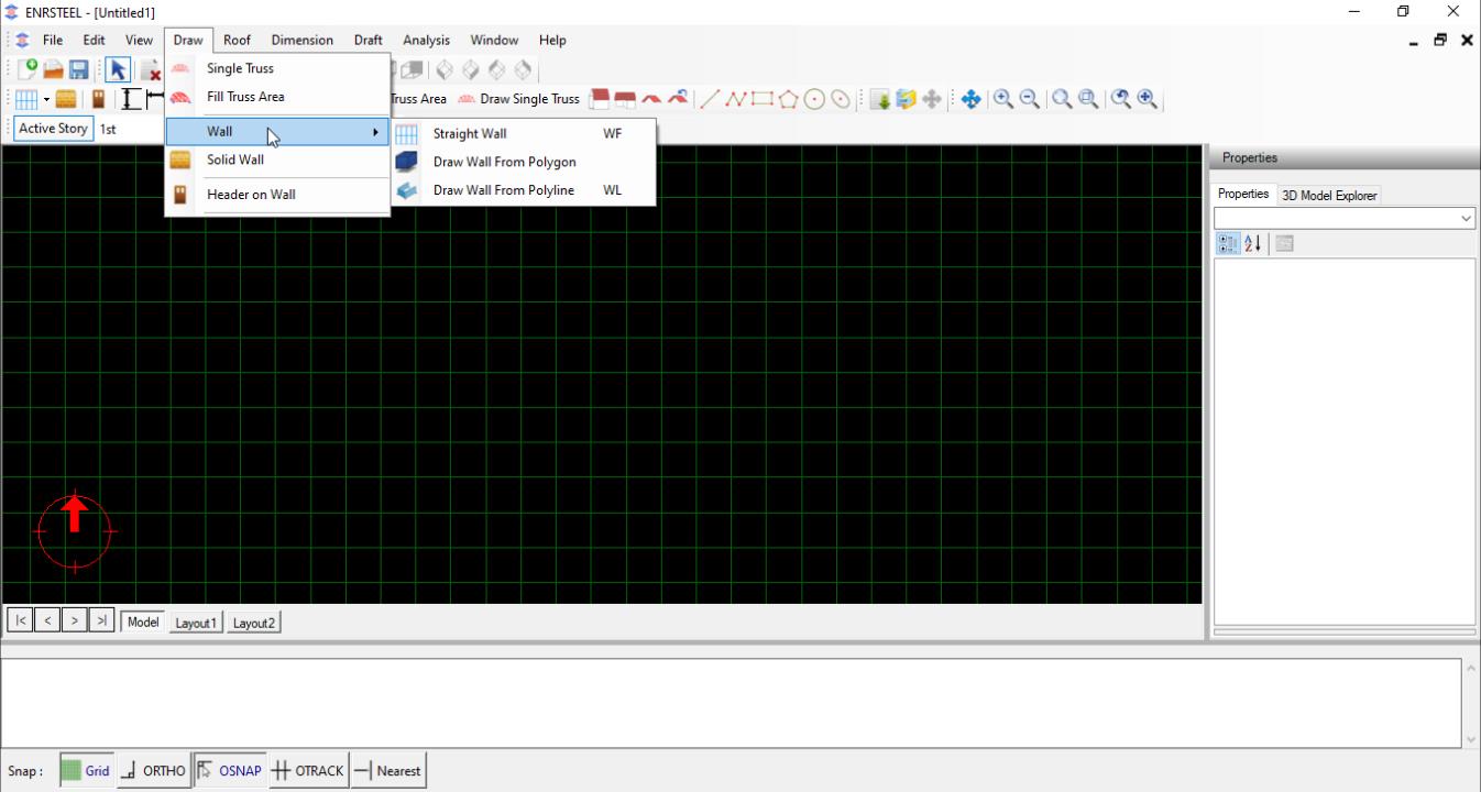
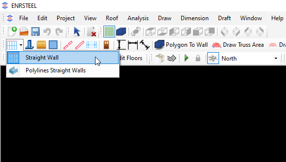
Users may access the wall command from Walls menu or toolbars. Toolbars options are explained below or by walls shortcut.
The function of a Solid Wall is to represent the existing building or to complete steel walls. We need it sometimes to show the shear line.
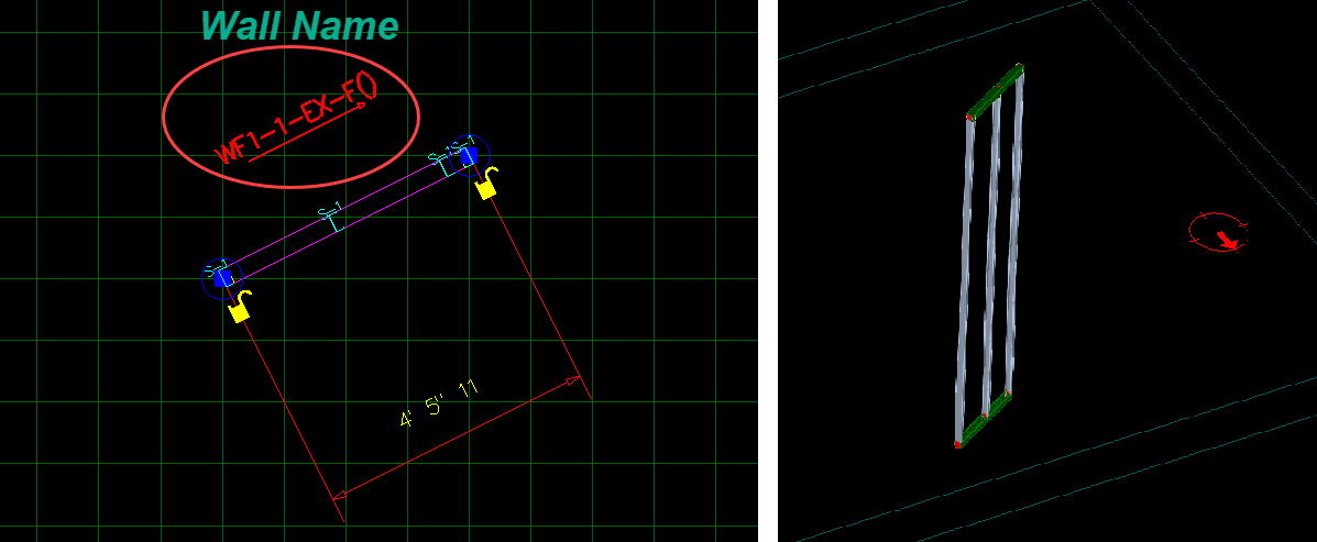
Straight wall
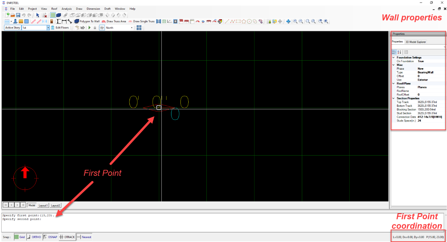
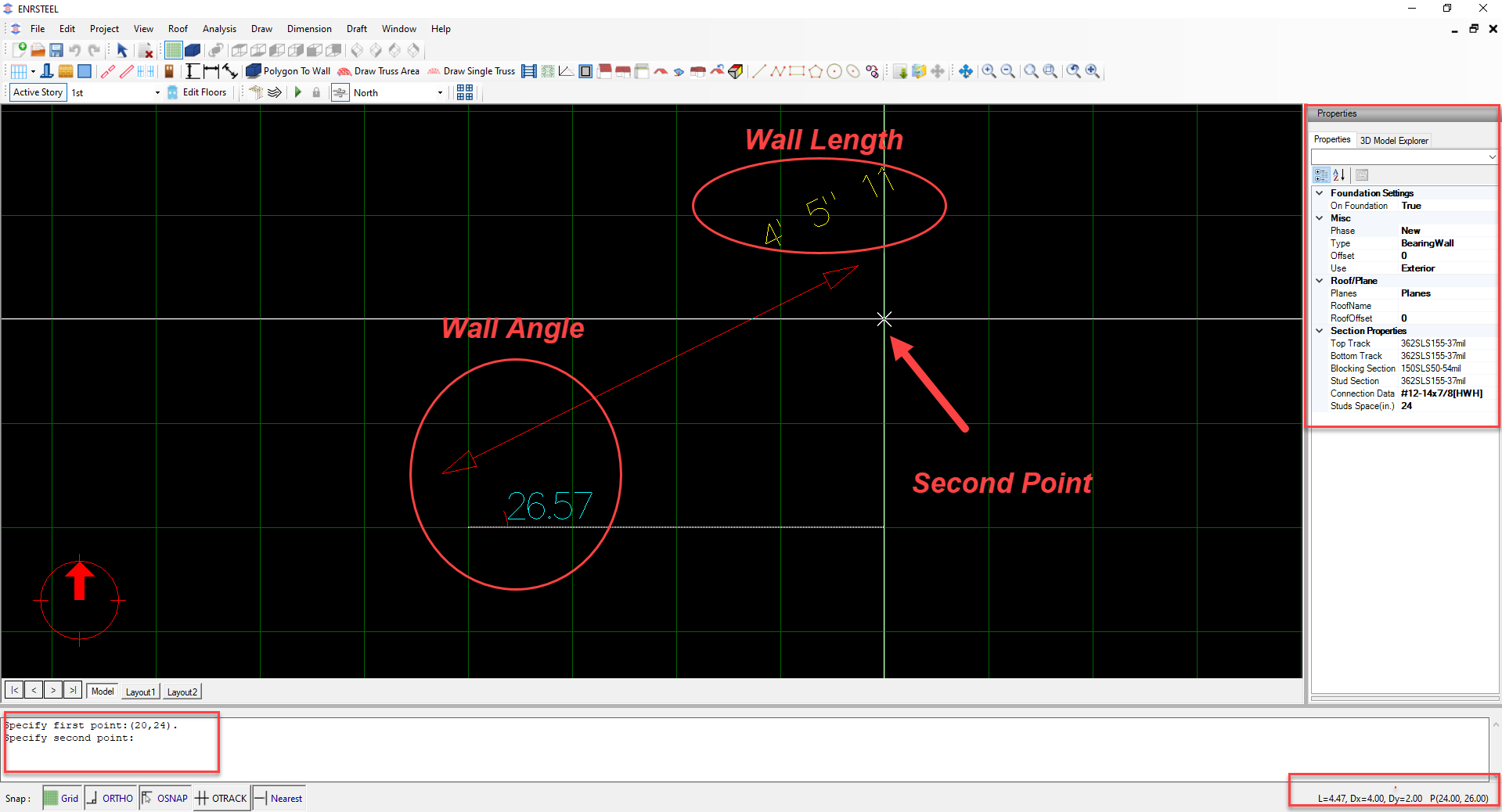
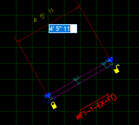
When selecting to add a wall, user will be promoted to select first alignment point, then the second alignment point. The third click will be used to position wall with respect to the alignment line. For example, for vertical walls users may position wall left, centered or right of the alignment line.
The program automatically assigns a WF wall ID to the wall (for exampleWF4 in the capture below). The complete wall ID will include a hint on whether the wall is exterior (EX) or interior (IN). If wall has a foundation, it will also include a hint of FDN.
Steps:

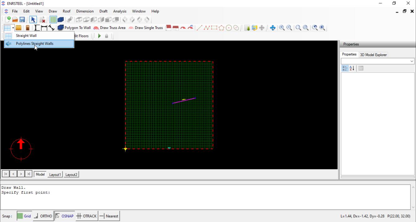
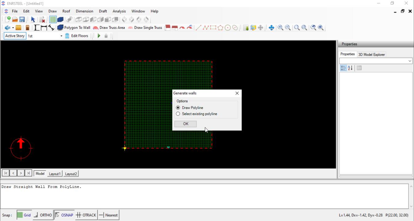
Walls by Polyline
This option generates walls along a polyline object. User can simply click at nodes of polyline and the program creates the walls. Wall thickness will be positioned according to the direction of drawing (right side of the direction of travel). FIG shows the resulting walls when drawing clockwise and counterclockwise.
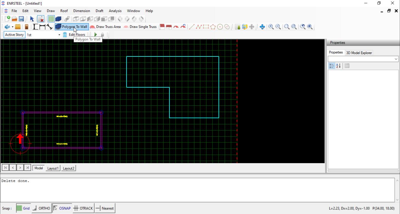
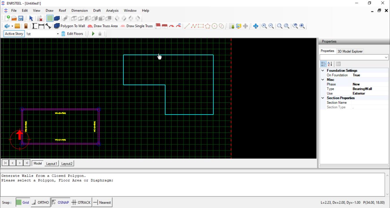
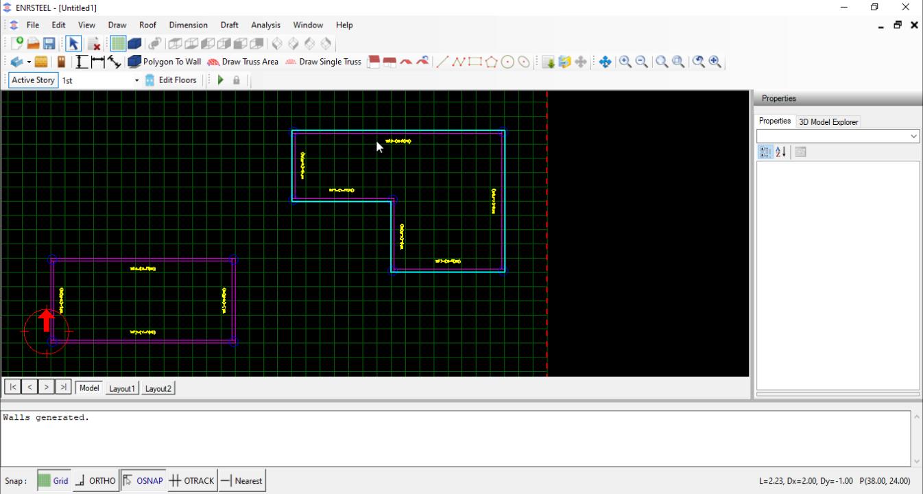
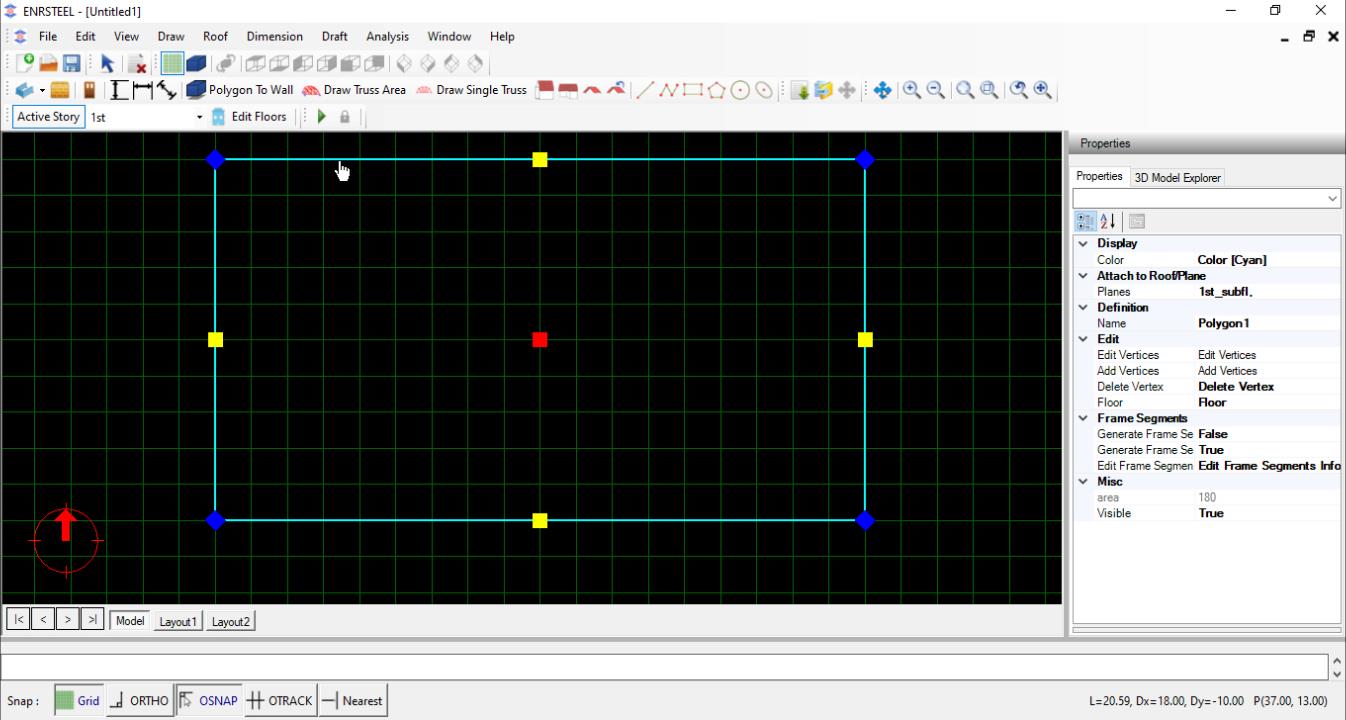
Walls by Polygon
This option will generate walls inside a polygon. The user can select an existing polygon object or an object that has a polygon around it. This option can be very effective in drawing floor quickly from existing objects. Capture below shows example of walls generated inside a simple drafting polygon.
Edit Walls
Note: unlock one end if you want to increase/decrease the wall in one dimension. If the lock was unlocked, then the dimension of wall will change in both directions.
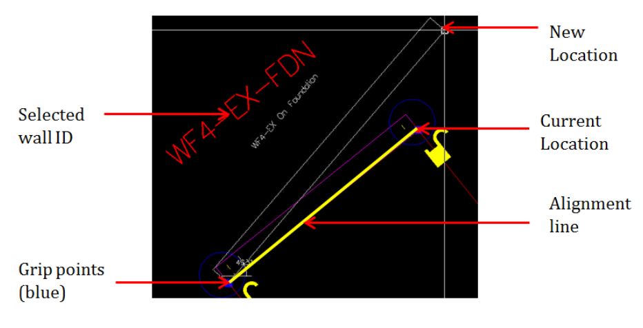
Graphic Editing of Wall Start/End Points
Once a wall is selected, the program highlights grip points (in blue color) at the start and end of alignment line of the wall. When user click on the grip point to be moved, the color changes to red indicating the point can be moved to a new location. Once user clicks at the new location, wall will be modified to reflect the coordinates. User can modify location of alignment line to facilitate the grip editing along certain lines.
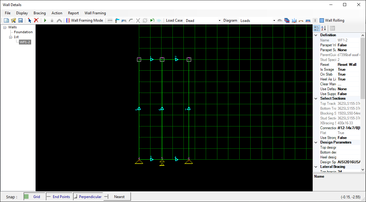
Users can reach wall details by click right click on mouse after selecting wall. The screen as in fig 31 will provide all details for that specific wall.
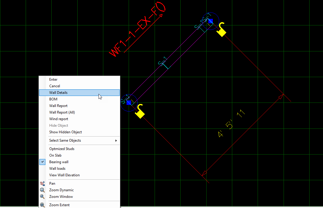
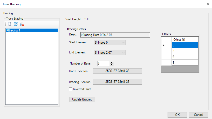
As shown in fig32 we can generate K-bracing walls from wall details window as well as we can choose the sections and number of bays – diagonal webs- and we can select the offset between the horizontal bars.
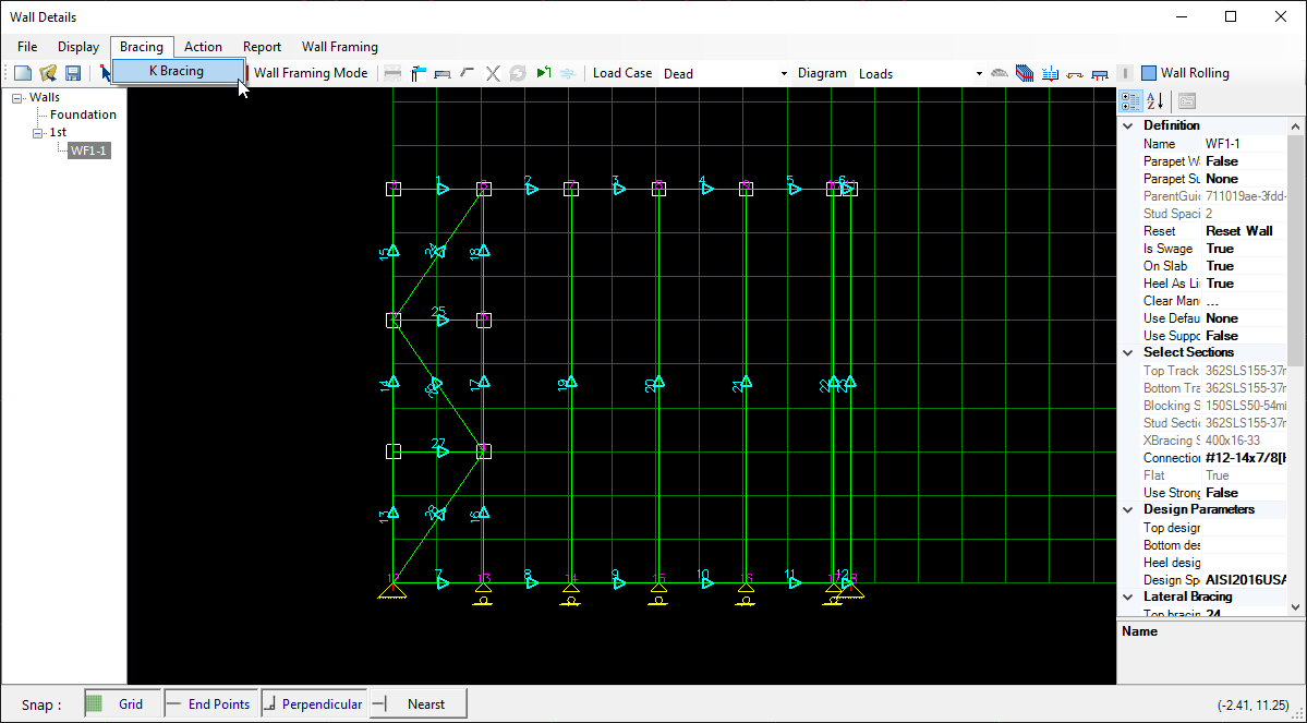
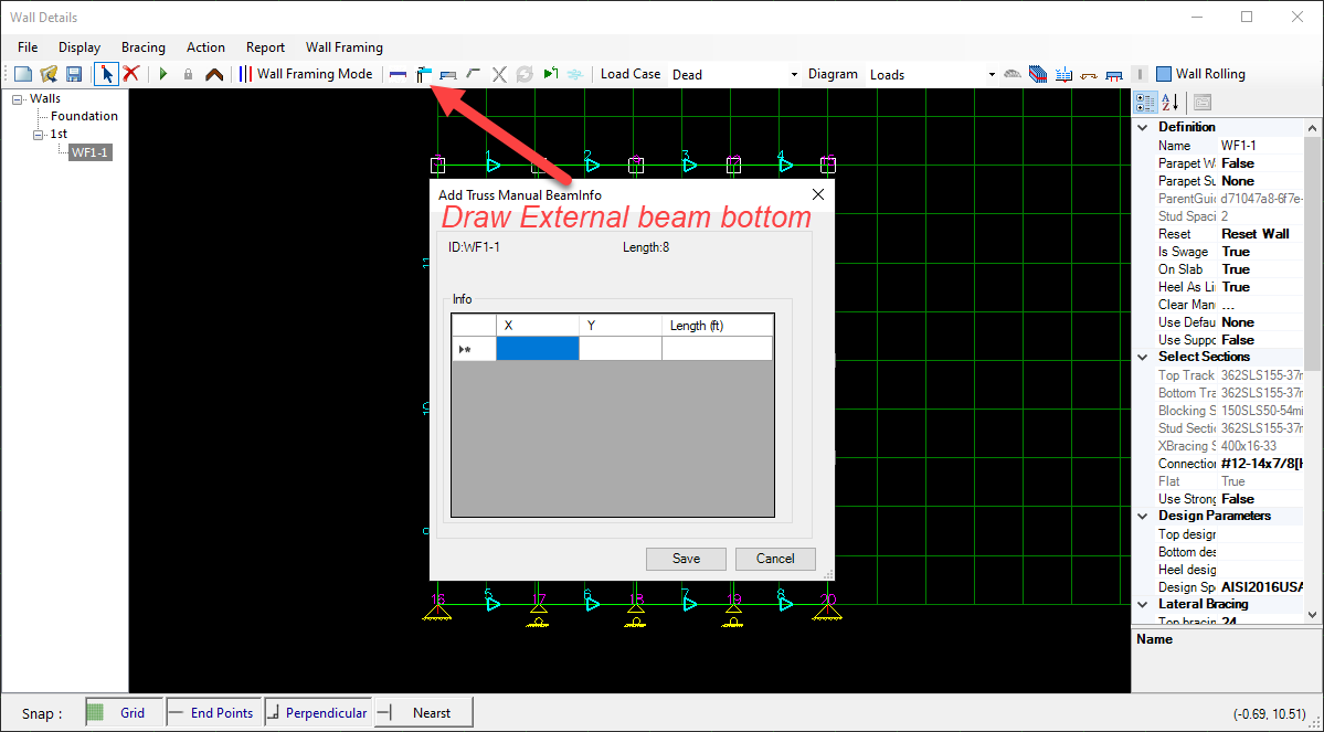
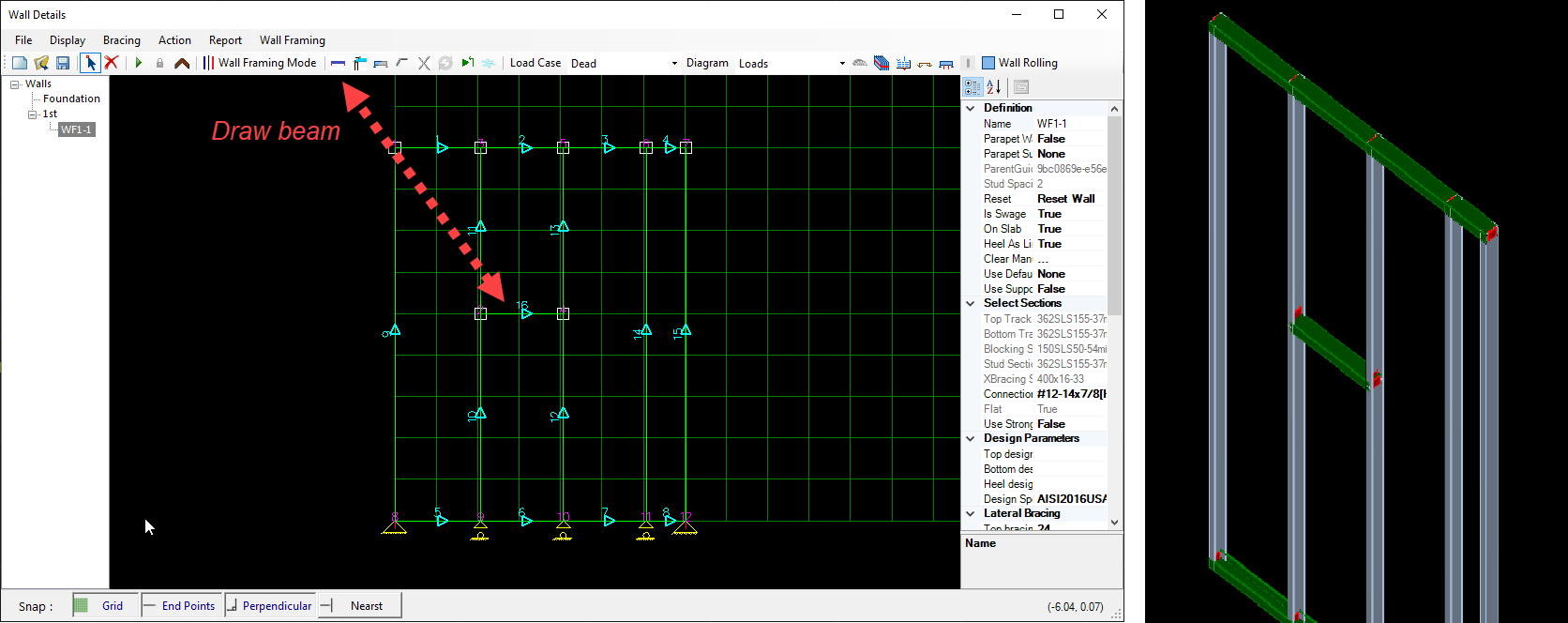
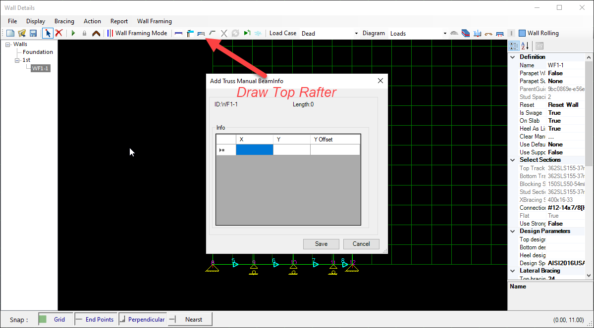
Icons for manual truss and wall rolling data

Wall Openings
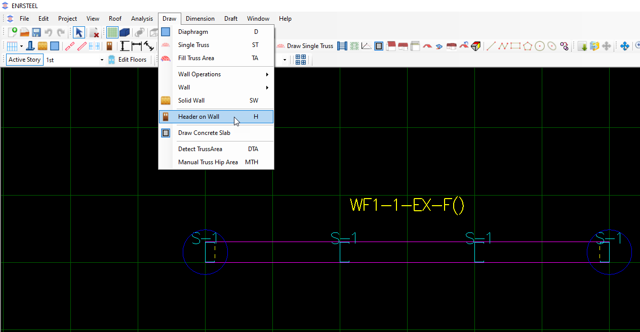
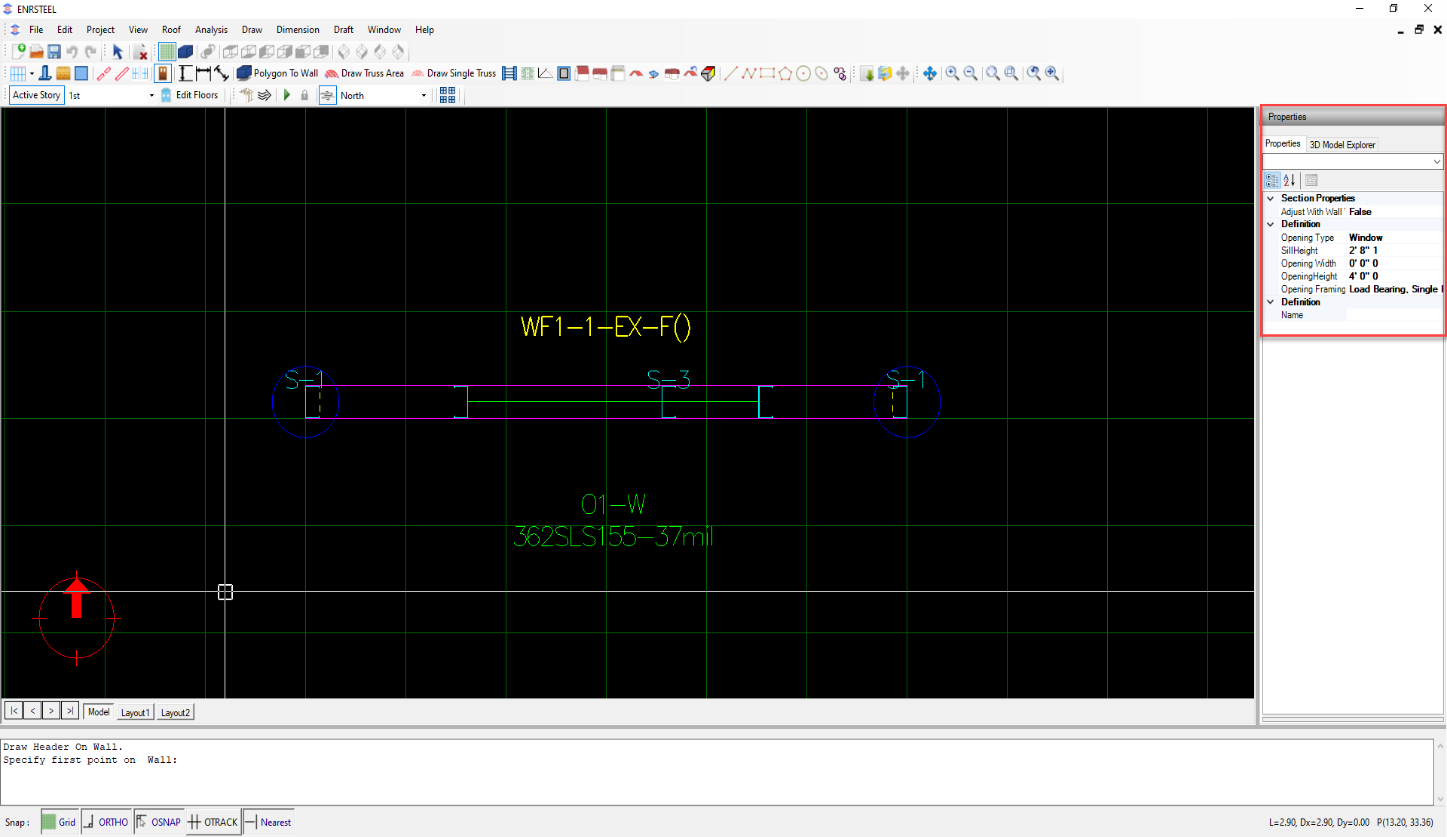
The Add Opening option under Walls menu or the Toolbar icon. Add opening toolbar can be used to create new wall openings. User will be promoted to click at start and end location of the openings along the wall.
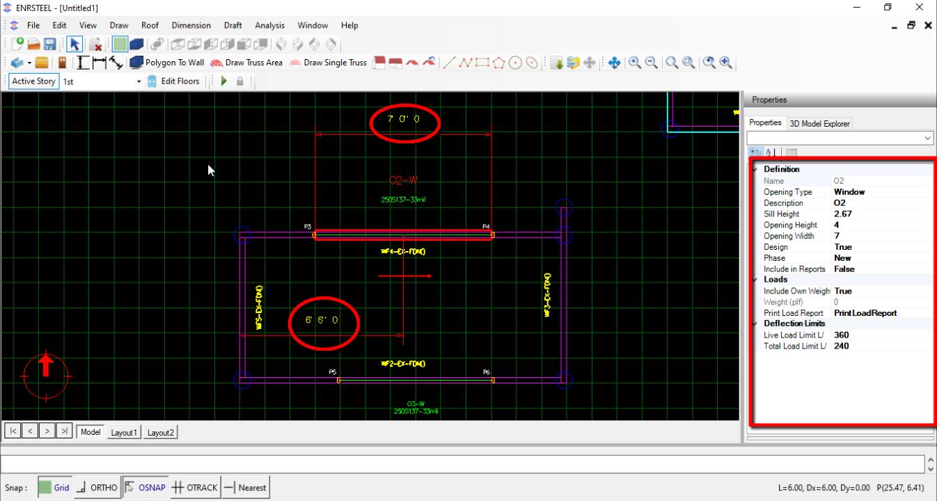
After opening is created user can edit size of opening or location of opening center line with respect to start of wall from property grid or simply clicking on opening dimension line and then input the new distance.

Edit opening
Edit opening from opening property and the dimension and location by edit dimension after selecting it.
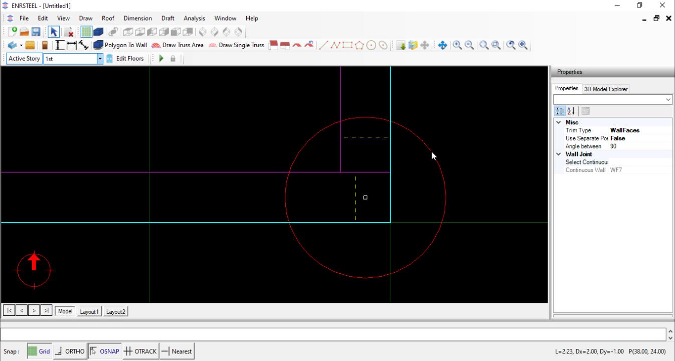
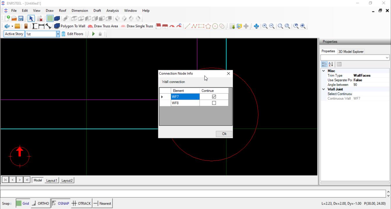
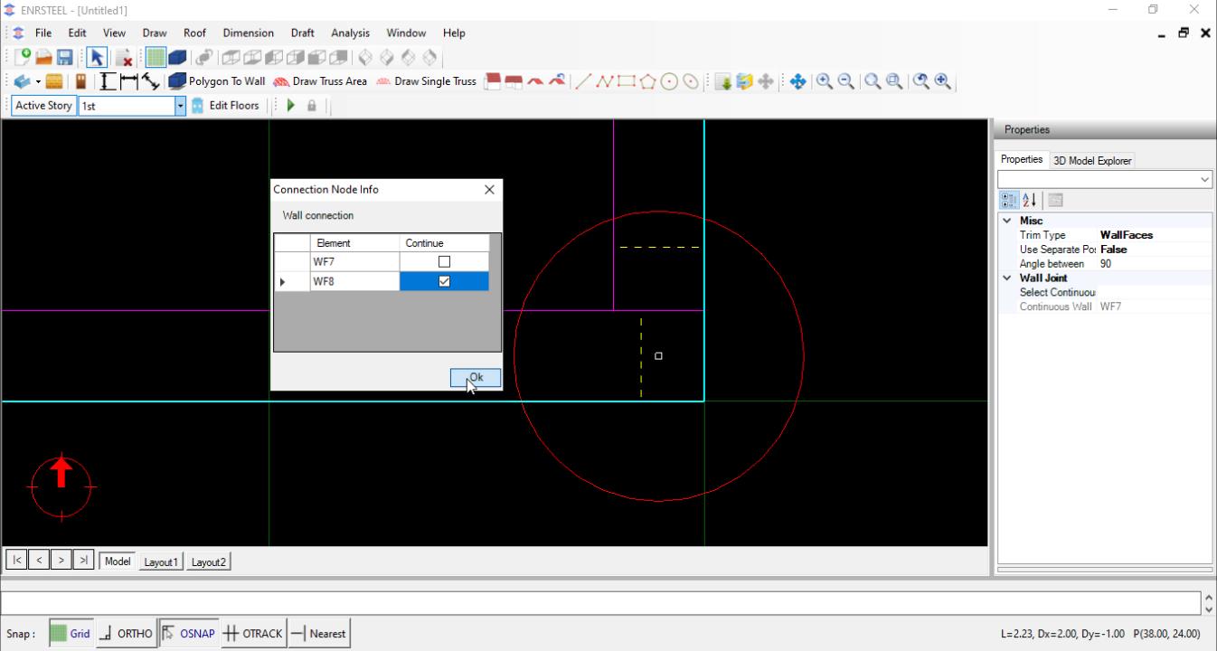
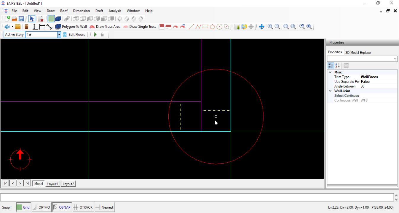
Wall Intersections
User can control wall trim by selecting which wall to continue at the intersections. User may use property grid after selecting the circle at the intersection. Alternatively, Right Click context menu of wall connection object provide quick access to edit connection properties including selecting trim type and continued wall.
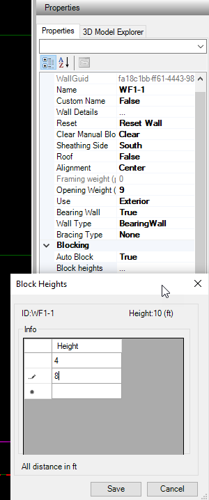
Note: Rest wall needed when we do any change at wall to take the order it work as refresh wall. Custom name to change wall name as you want.
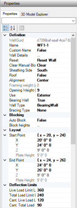
Users can easily control of wall Alignment from Top, Bottom and Center to change wall place or connect it with other elements.

Users can choose the function of wall if it will be Exterior (EX) or Interior (IN). That is matter for load distribution when if effect to wall and we can see that clearly when we print the report and look at loads part. Each wall has specific name as the following:


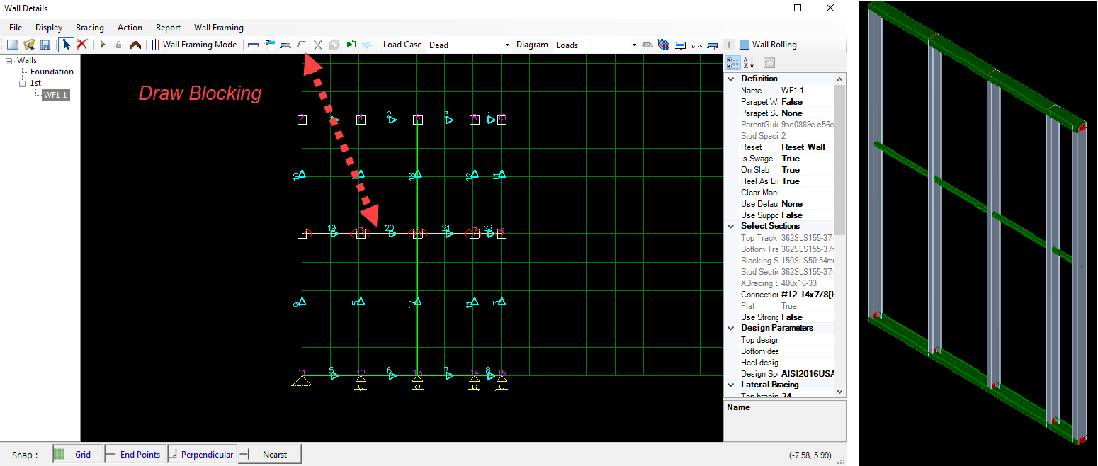
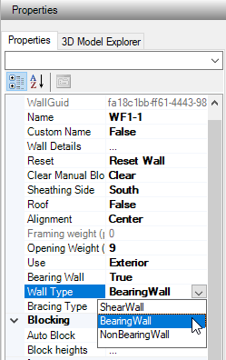
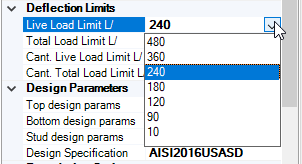
For Wall Properties users can select Wall type fig 33, Bracing type fig 34, add Blocking at specific height if needed fig 35 and select the deflection limits as shown in fig 36.
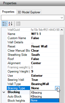
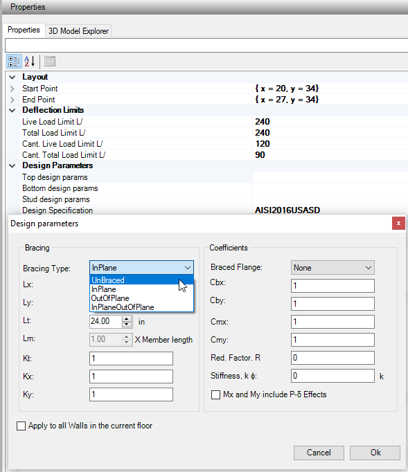
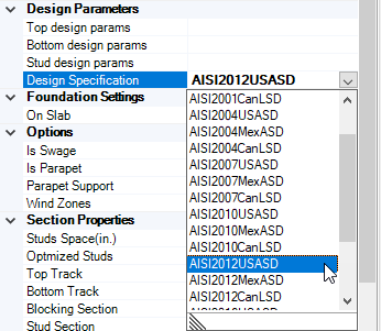
From design Parameters Users can choose bracing type for walls as well as they can change the bracing sittings and coefficients. The available codes its American, Canadian, and Mexican. Soon the European code will be added. Fig 37, 38.
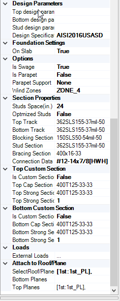
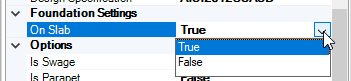
If Users hit On Slab button as True, each Stud will has!!! support connected to the slab floor.
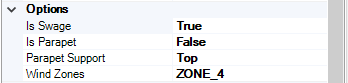
Swage stud section in rolling
The wall parapet or not
The parapet is hinged from bottom or top
Wind zone for wind calculation
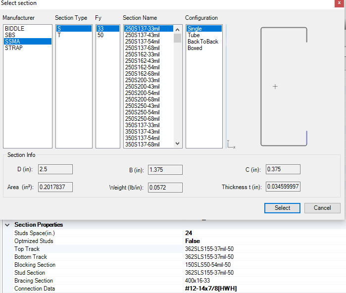
Section prosperities allow us to choose Stud spacing in inches select section from the available libraries and Configurations for each of Stud, Top track, Bottom track, Blocking and Bracing also, the Connection data. !!!!!!! Optimized studs mean adding stud under each truss or joist floor. This option is great to save material of top track

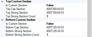
Generate custom shape of top and bottom track
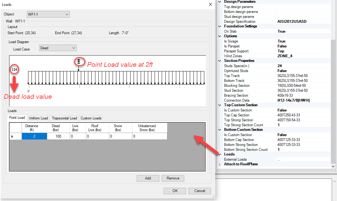
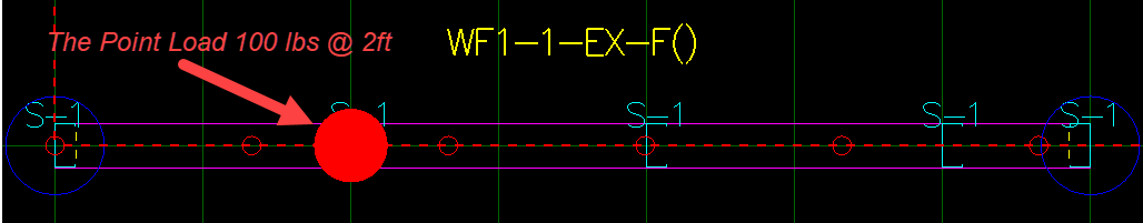
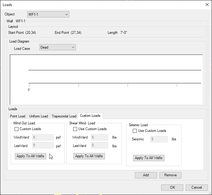
From Loads tab Users can add point load at any distance, Uniform load Trapezoidal load and use Custom load if they needed to insert it manually. Point loads will appear as red note on wall fig 39. Also we can choose load case to be as Dead, Live, Roof Live Load, Balanced Snow or Unbalanced snow.
Note: Look at loads chapter number 5 to see loads details how it represents in reports.
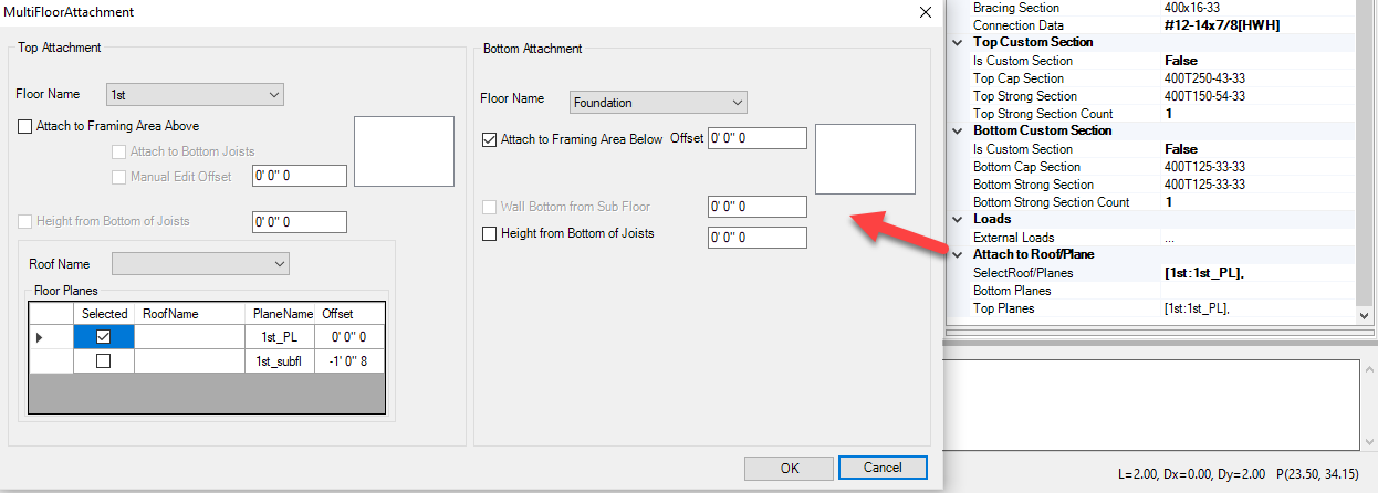
Attach to Roof/Plan helps Users to adjust Walls attachment to increase/decrease wall length as needed from Top or bottom. Don’t forget to reset wall after fixing wall attachment.
Roofs
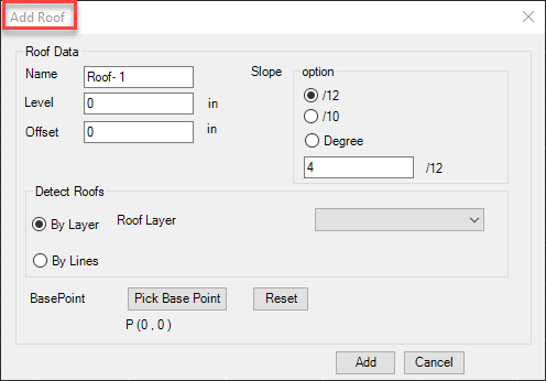
Add Roof
Users can create Roof by 5 ways:
- Roof from Polygon (RP)
- Roof from walls (RW)
- Roof Plan (DP)
- Import Roof from AutoCAD using ENR 3D.
- Import DXF Roof.
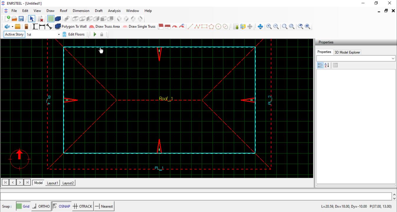
Create Roof from Polygon
This option will generate roof from a polygon as roof boundary. The user can select an existing polygon object or an object that has a polygon around it. This option can be very effective in drawing roof quickly from existing objects. Capture below shows example of roof generated inside a simple drafting polygon.
Create Roof from Walls
This option will generate roof from a closed wall. The user can select an existing wall to use it as boundary of roof. This option can be very effective in drawing roof quickly from existing walls. Capture below shows example of roof generated inside a simple drafting polygon.
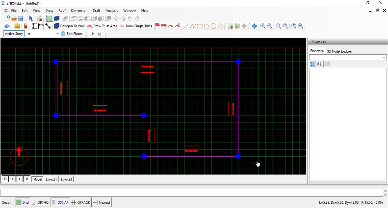
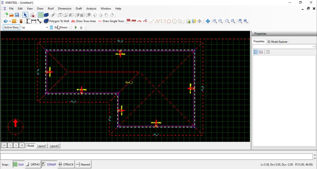
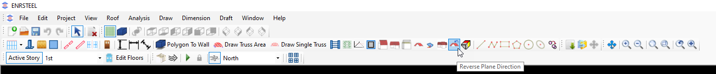
Create a Roof Plane
When selecting to add a roof plane, user will be promoted to select first alignment point, then second alignment point. The third click will be used to position plane direction and boundary.
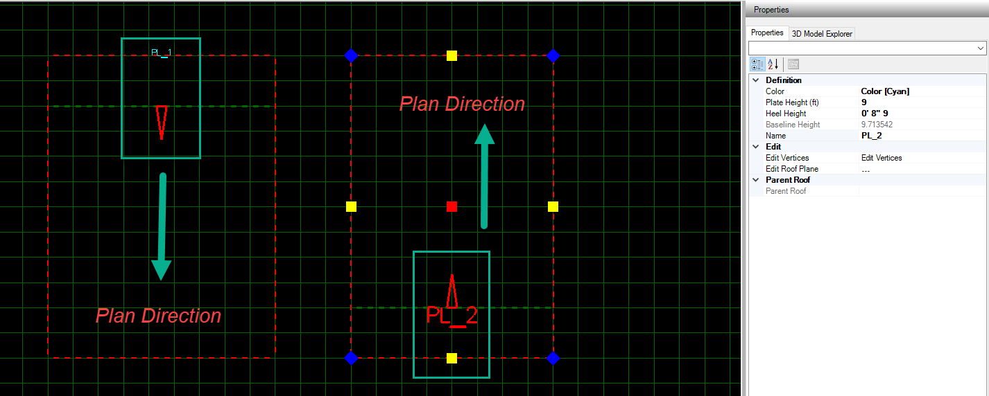
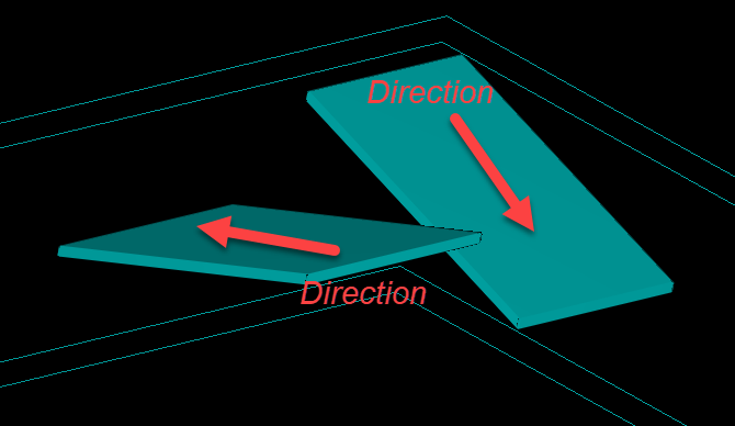
Note: there is an option allow us to reverse plan direction.
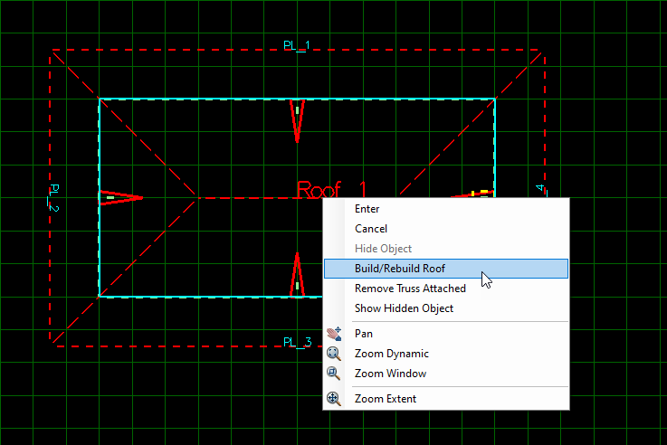
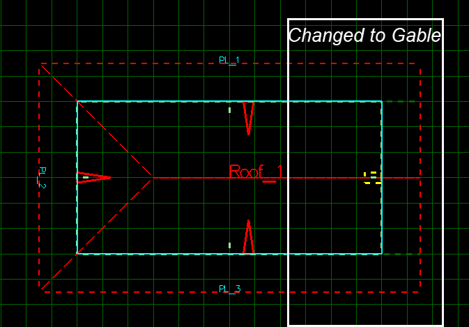
Edit Roof/ Plan
Users could Edit Roof/ Plan by many ways as the following:

Single Truss
Note: To draw any element in ENRSTEEL there is 3 ways:
- Click on the icon which represent the function directly from Toolbars.
- From menu bar go to draw tab then select what you want to draw.
- Write the shortcut for what you want to draw in the modeling area then hit enter or right-click on the mouse. See the shortcuts abbreviation at the end of this guide.
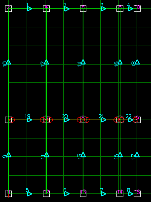
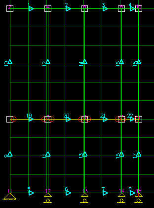
Note: The shortcut for Single Truss is (ST).
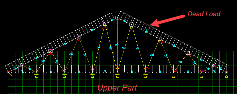
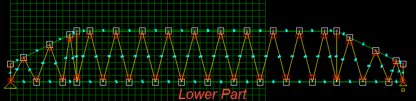
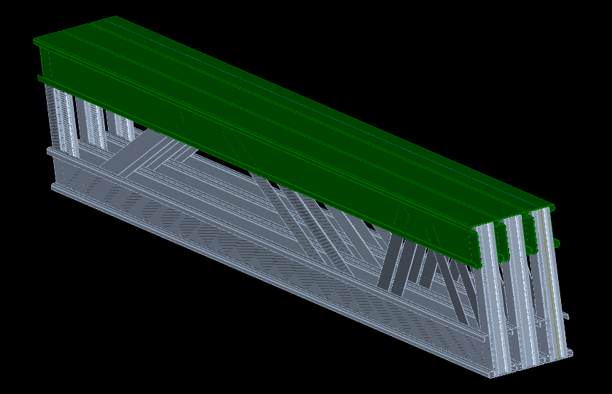
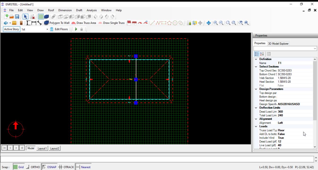
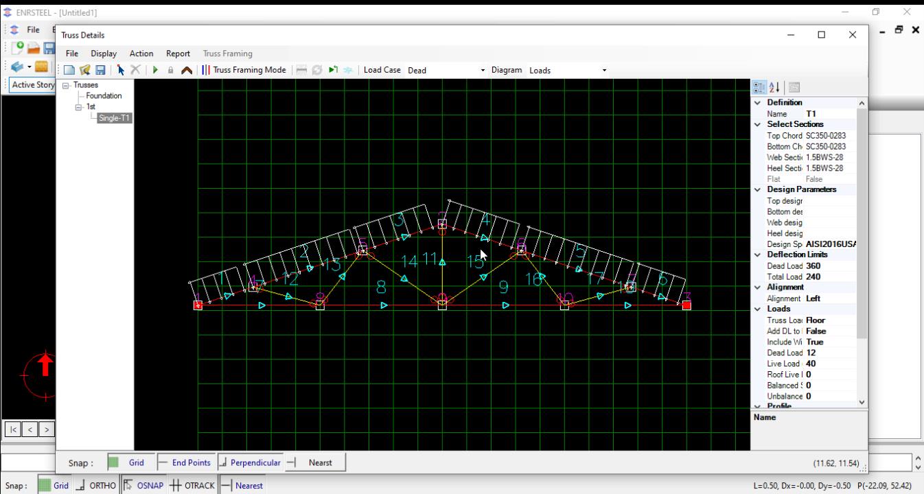
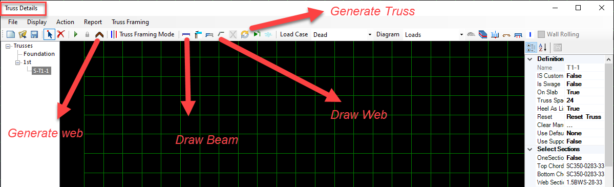
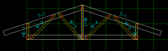
The below figures show the Single Truss in 2D & 3D with truss components.
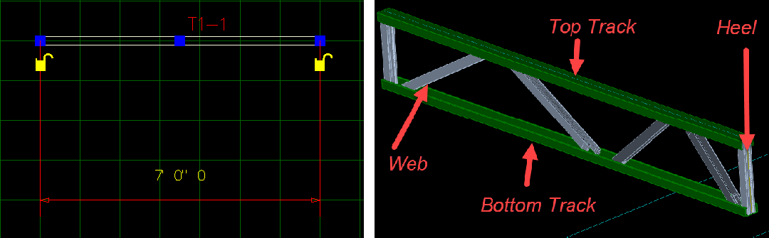
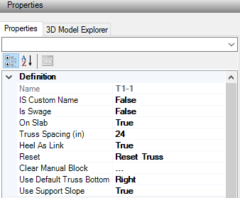
For Definition section in Single Truss the Properties will be same as Wall the additional here is Use Default Truss bottom which allow us to connect the top track and bottom track together from Right, Lift or both sides. Also, we can add a Support slope.
For Single Truss Section we can pick any of our library as well as if we select One Section button as -True- the sections will remain same and will not go up even if it failed.
Use Strong Inertia allow us to control of Top/Bottom tracks directions to be as Strong Inertia -False- (Weak axis) or Strong Inertia -true- (Strong axis) as shown in fig 42 & 43


Sometimes while designers work on project, they need to have a Ply truss count they can add trusses as needed. Fig 44 & 45 show that. The Piggy Back Trusses could be created after determine the correct elevation for cut and draw plan there to attach trusses to it.
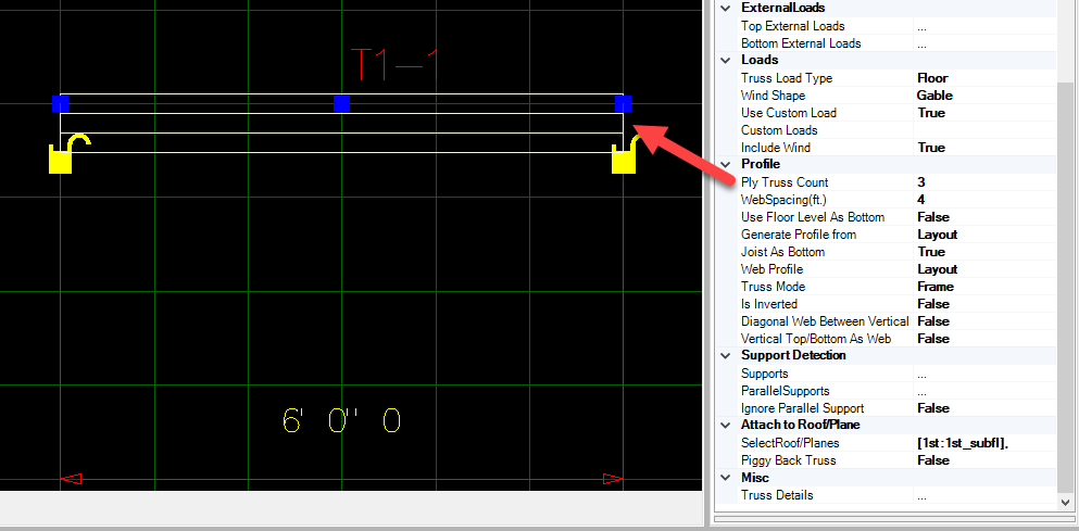
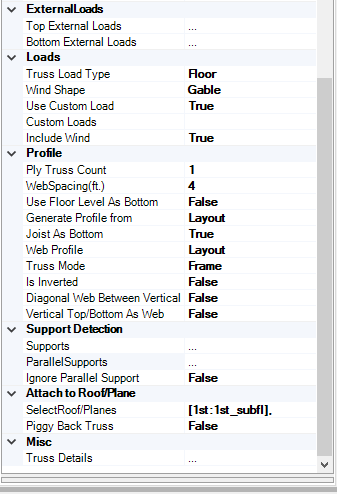
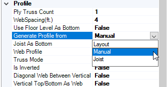
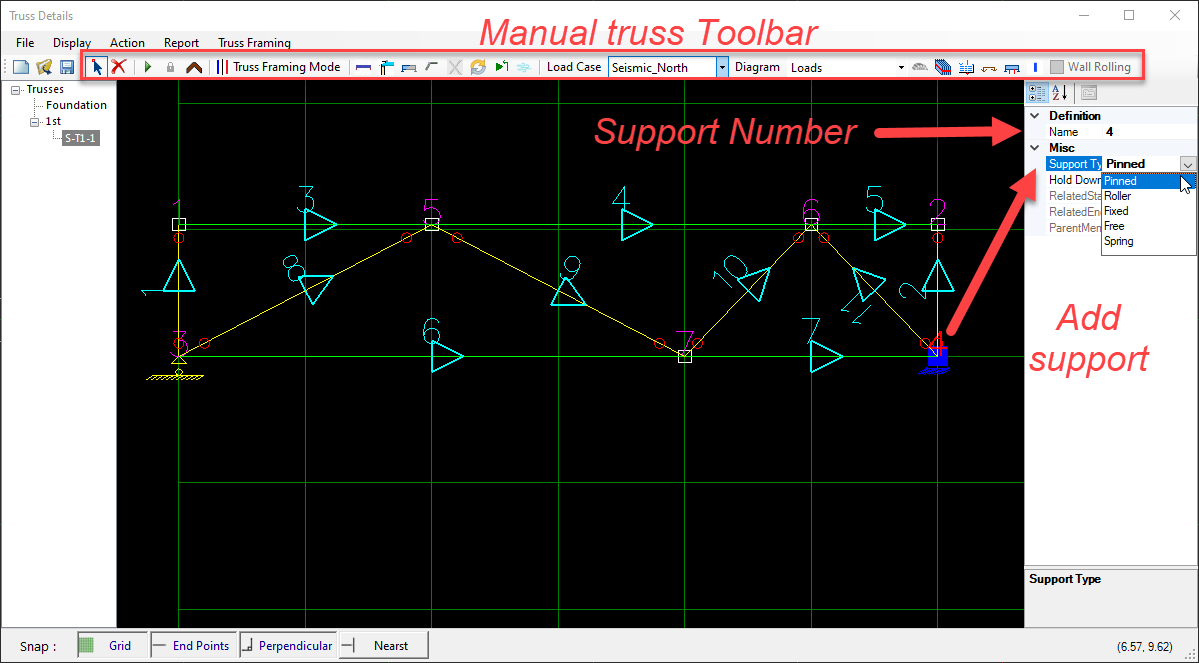
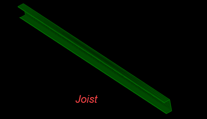
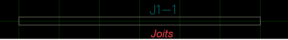
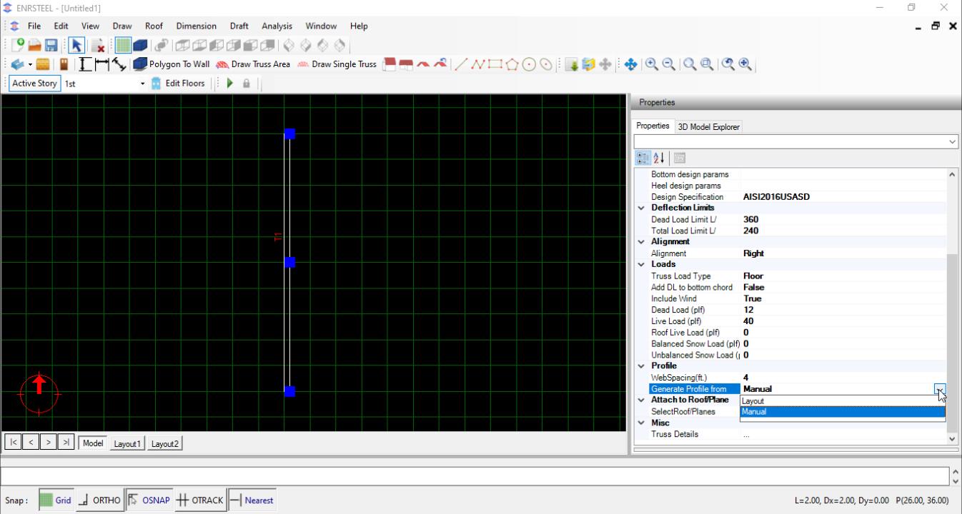
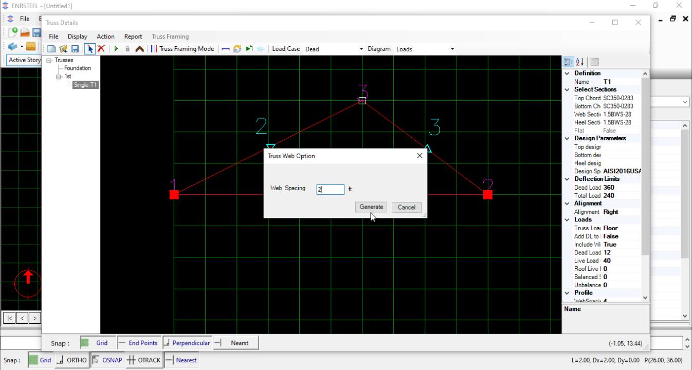
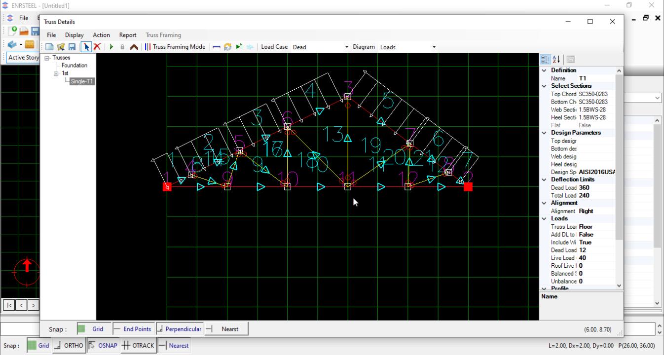
For Generate Profile Form we have 3 options the 1st one is Layout which allow to software to Generate the Truss automatically, the 2nd option is Manual and here we can redraw the truss members add or delete members from manual truss toolbar also choose the hold-down and supports as designers needs after we select the truss name and open truss details, the 3rd option is Joist. In this case, we will have only track as in fig 46 & 47. Web spacing can be changed.
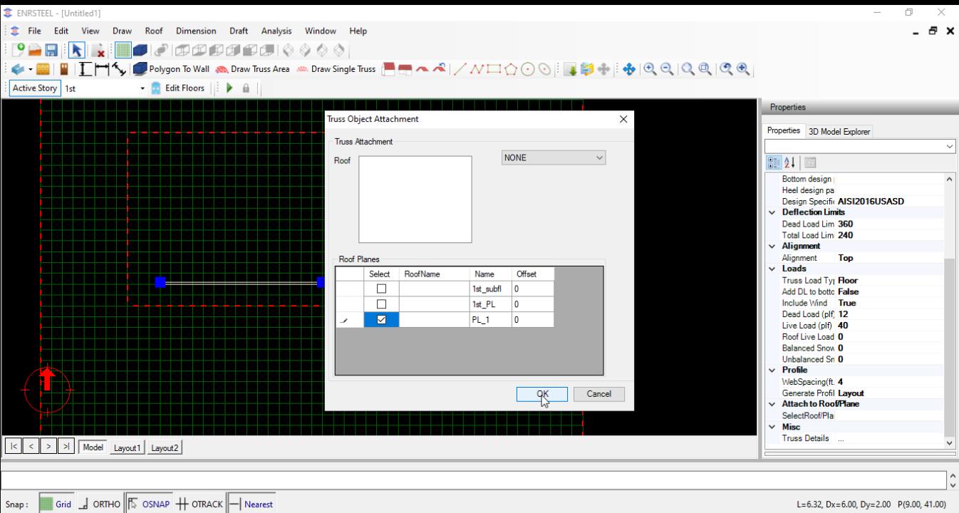
Single Truss attachment
Single truss need to attached to Roofs/plane tend to reflect the shape and framing system. Following examples shows truss area attachment.
Attached to plane
Select truss and click “Attached to roof/ plane” and attached to “PL” plane
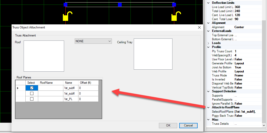
Attached to slope plane

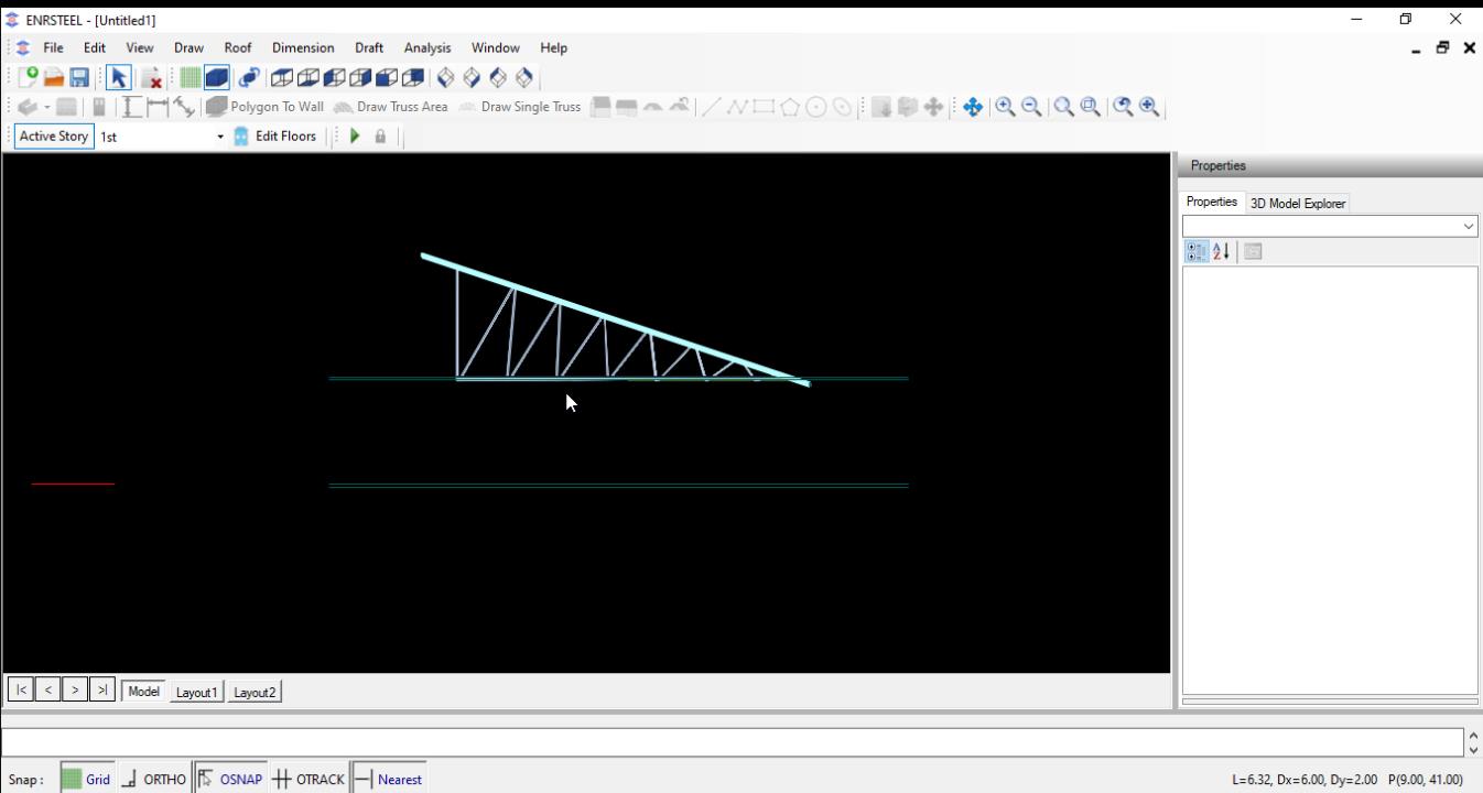
Attached to roof
Manual Truss
Add Manual Truss
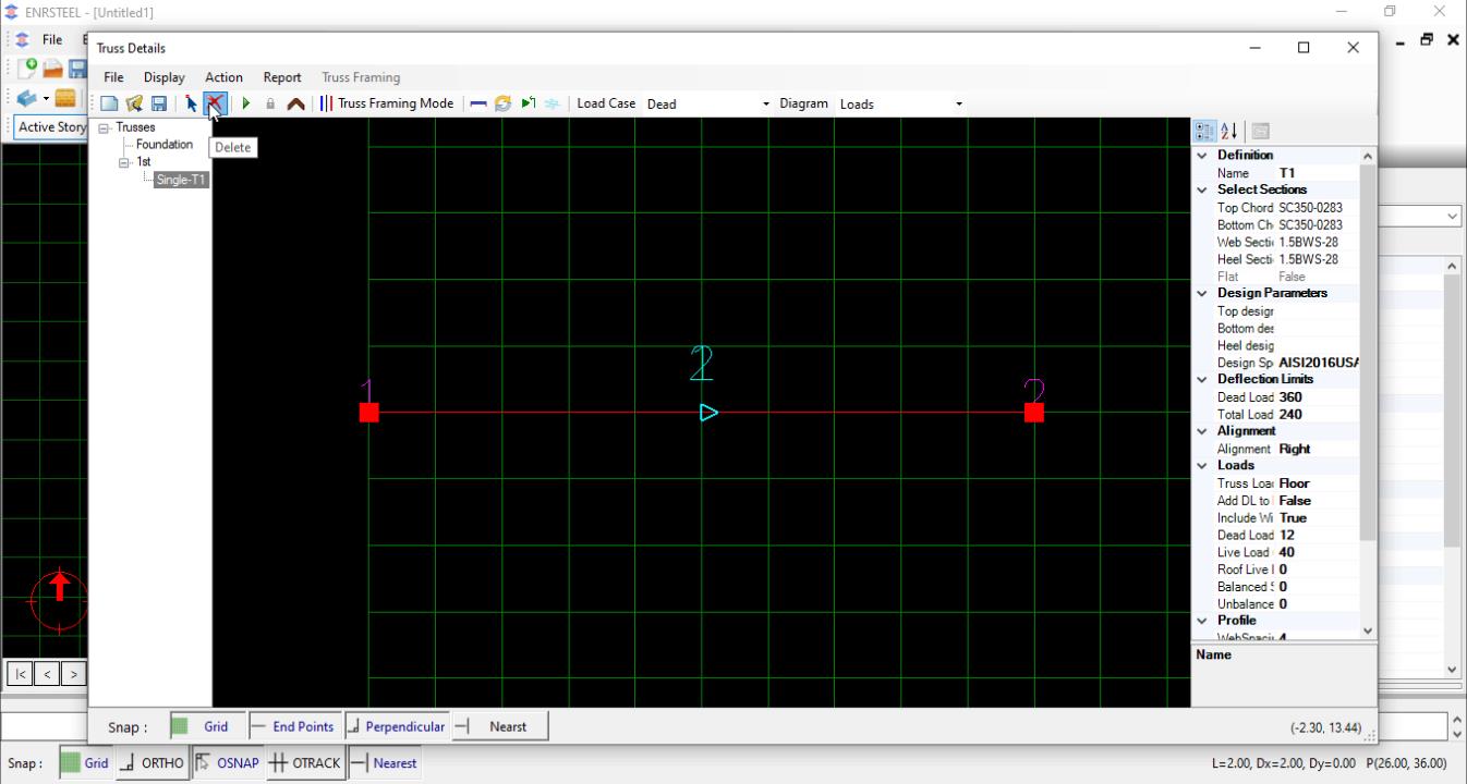
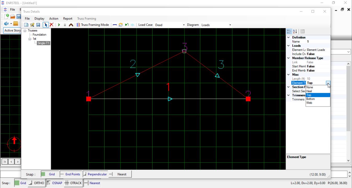
Users can modify/create the envelope of any truss of truss area or single truss by changing generate profile property to “Manual”. Open truss details to complete the envelope of truss. See steps:
Note: Users could import any truss profile from AutoCAD if they already drew it there and the software will draw it as it is and engineer it after selecting the sections and adding loads. And they can export it too to AutoCAD.
Truss Area
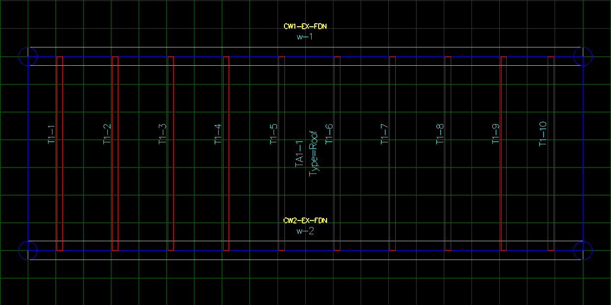
Fill a certain area with trusses. The user can select an existing polygon or draw polygon/rectangle to use it as boundary of truss area. The trusses have been automatically generating according to truss spacing and each truss has a label.
Note: To draw any element in ENRSTEEL there is 3 ways:
- Click on the icon which represents the function directly from Toolbars.
- From the menu bar go to draw tab then select what you want to draw.
- Write the shortcut for what you want to draw in the modeling area then hit enter or right-click on the mouse. See the shortcuts abbreviation at the end of this guide.
Note: Most of the single trusses properties apply to the truss area.
Note: The shortcut for Single Truss is (TA).
Flat Truss Area
In each story, there are two planes
The attached truss area to one of them makes a flat truss
!!!! Attached to “Story name _PL” needs offset
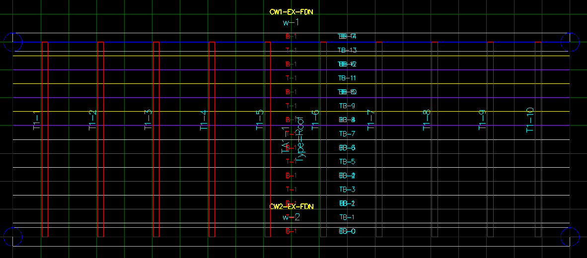
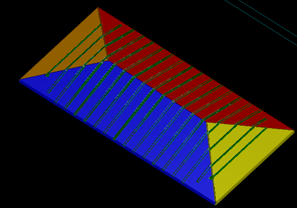
The fig 49 & 50 show the Truss Area in 2D & 3D with truss components
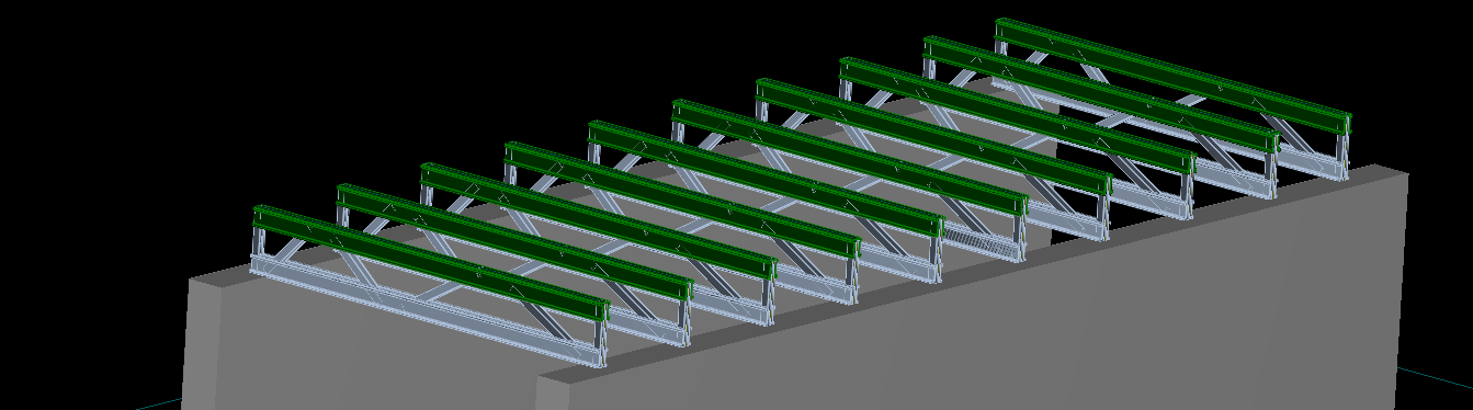
The following it’s a truss area window. There users select to draw truss area as rectangle or from polygon, to insert angle of rotation for trusses, spacing between trusses and web spacing. Also, there is 2 options to add roof or walls as supports underneath automatically.

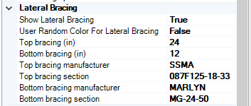
Each Truss Area allows us to add a lateral bracing on top and bottom and choose the distance between bracing bars and sections. Look at fig 51. Definition section provide many options which need to change truss area and select first and last truss starting or ending. Display section for truss appearance.
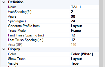

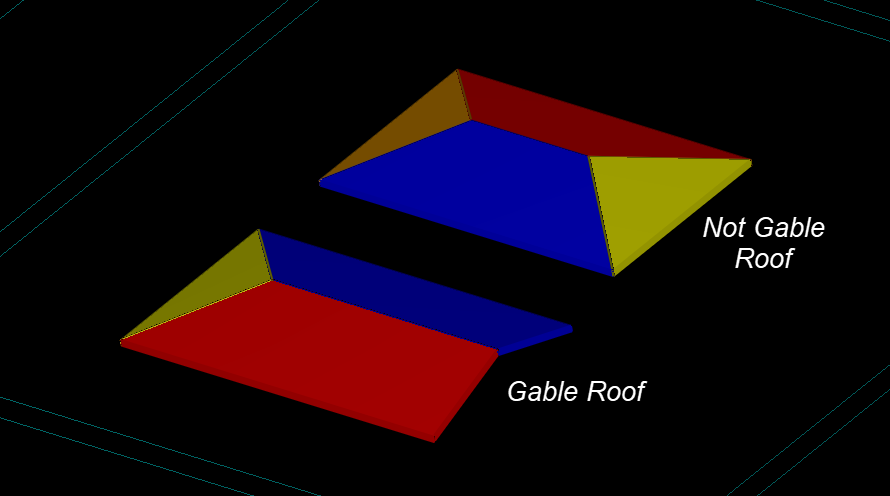
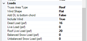
For Loads sections in Truss Area Type we can select on of Roof, Floor, Ceiling and wind shape we can select Hip, Flat, Mono Slope, Gable and None.
Truss Area Attachment
Truss area need to attach to Roofs/plan tend to reflect the shape and framing system. Following examples shows truss area attachment
Attach truss area to Roof/Plan !!!!
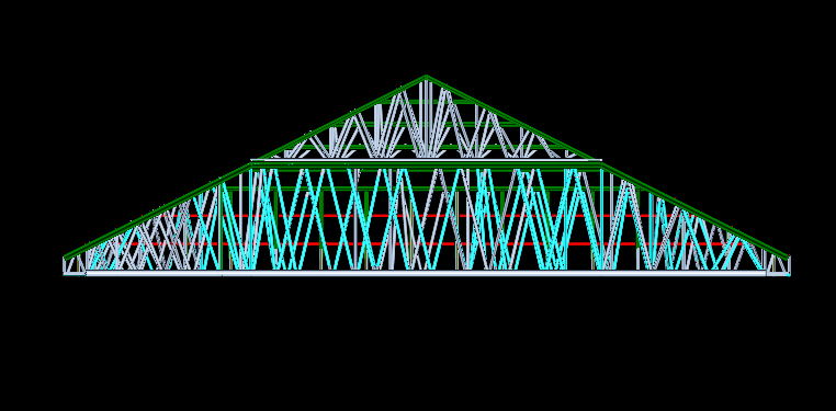
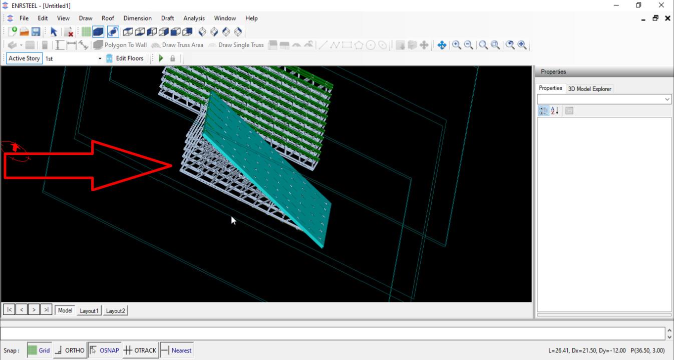
In Prosperities under attachment section to attach truss area to roof/plan they have to be drawn firstly then we draw a truss area at the border of that roof or plan. The last step to attach that truss area with it to take the correct shape automatically. Fig 52 explains attach trusses to roof and fig 54 explains attach trusses to plan.
The previous figure show us how the truss profile will look like under attached roof.
The previous figure show us how the truss profile will look like under attached plan.