User Interface
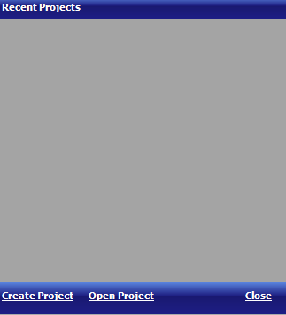
Starting Form
Starting form shows recent project, create project and open project.
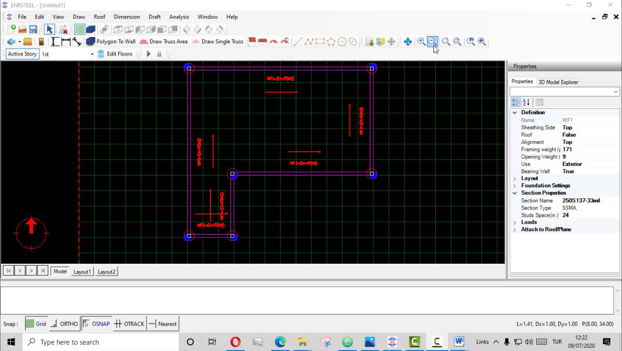
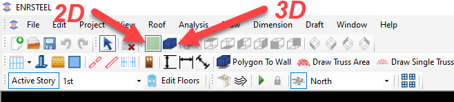
General Layout
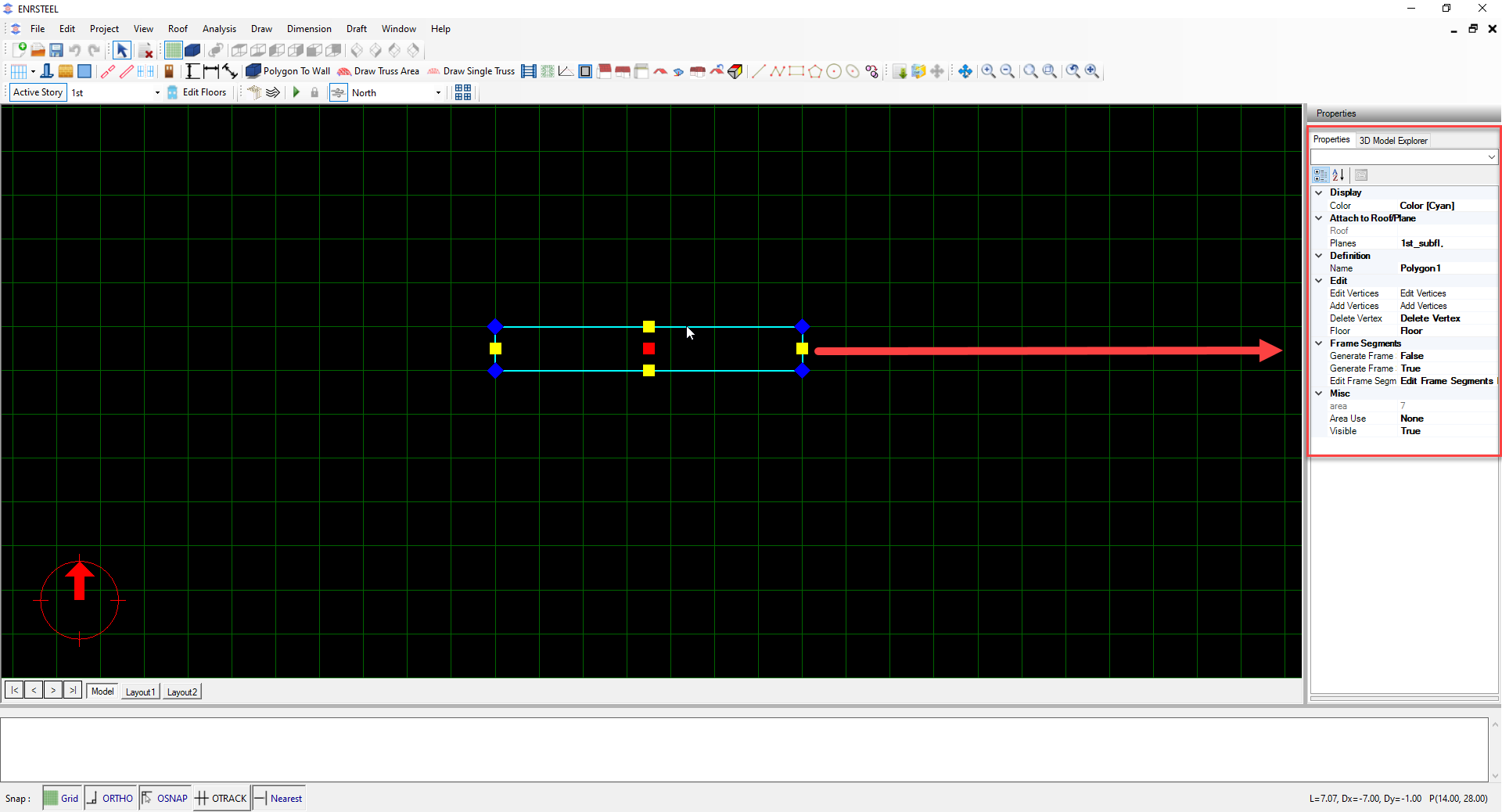
The general layout of the User Interface in ENRSTEEL.
Menus: The menus at the top of the software window are the typical menu-type interface.
Toolbars: Below the menus are the shortcut toolbars populated with icons used to initiate many of the most common user actions. If you hold the mouse cursor over a toolbar icon, a short description of the action will be displayed.
Modeling Area: The modeling area of the user interface is the main window to view the 2D and 3D of the model you are creating.
Object Properties: When an object is selected in the graphical modeling area, the object properties area will show many properties of the object. The object properties are organized in a tree hierarchy with some branches of the tree not expanded by default. Typically properties can be edited by left clicking on the property value in the right column of the object properties pane.
Hint Area: The white space near the bottom of the software interface is an area where messages to the user are displayed. One common use of this area is to display information, or hints, to the user during a multi-step editing action. This area is also used to show the status of the analysis process.
Snap Control: The buttons of the snap control area at the bottom of the interface are a very useful way to change the behavior of the cursor and selecting points within the graphical modeling area. The behavior of selecting points is similar to many CAD tools where the user can snap to points orthogonal to objects (Ortho) or end and corners of existing objects (OSnap).

Navigating Within The Modeling Window
Use of a three button mouse with a center wheel is a highly recommended for efficient use of ENRSTEEL. The rolling the center wheel zooms in and out in the modeling window. Pressing and holding down the center wheel/button and moving the mouse pans the view of the model. A user who is familiar with these two actions can very quickly navigate around a model.
A quick way to edit the geometry of a model element is to select the element by clicking on the label which causes the vertices of the element to be displayed. The user can click on any vertex to select the vertex and click at a new location to move the vertex. Combined with snapping to CAD background, this is a quick way to modify geometry. If the user has selected a vertex to change its location, but decides against moving the vertex, pressing the “Esc” button will cancel the move in progress.
Editing Model Object Properties
ENRSTEEL provides object data and editing options in a single location under object properties explorer on the right side of the program window. User can browse through different properties to make adjustment without the need for multiple menus or toolbars. When a single object is selected, the full range of properties and editing options are shown in the object property explorer. In addition, several similar objects can be selected and edited at once. To select multiple objects, first select one object by pointing the cursor on it and clicking the left mouse button. Then press and hold the key and continue selecting additional similar objects by pointing the cursor on those objects and clicking with the left mouse button. In addition to viewing and editing the object properties using object properties explorer, many commonly used properties are accessible by context-sensitive object menus that are available by right clicking on the modeling objects. Both the object properties browser and the right-click menus change when viewing analysis and design results.
Menu Bar Breakdown
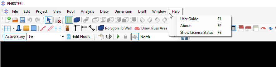
In this part, the user will be able to know about each cell in the menu bar and what is included.
From the File cell, we can create a new project -New-, open a previous project- Open-, save any changes in the current project -Save-or save the file as a new file with a different name-Save As-.
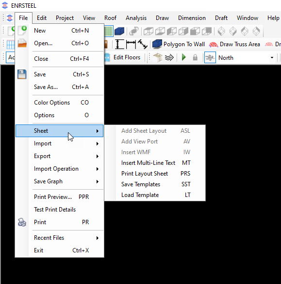
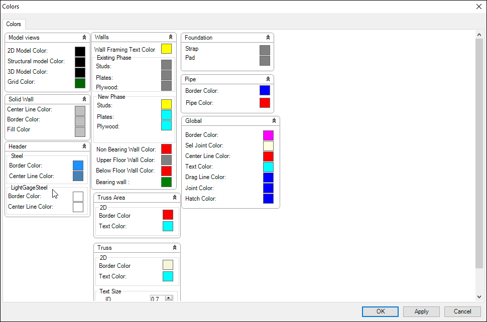
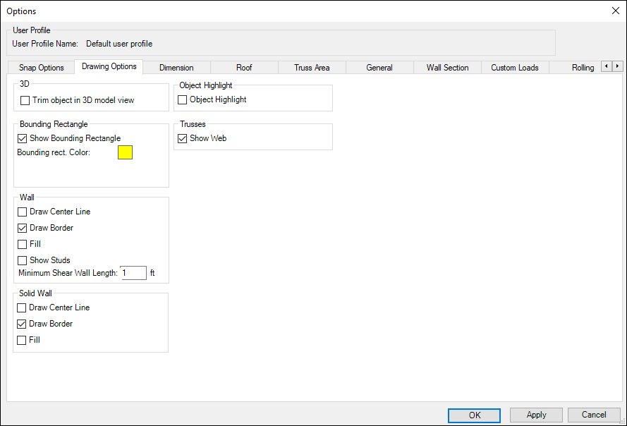
Also, the user will be able to change drawing colors from the – Color Option- button. The figure below represents the available changing and text size as well.
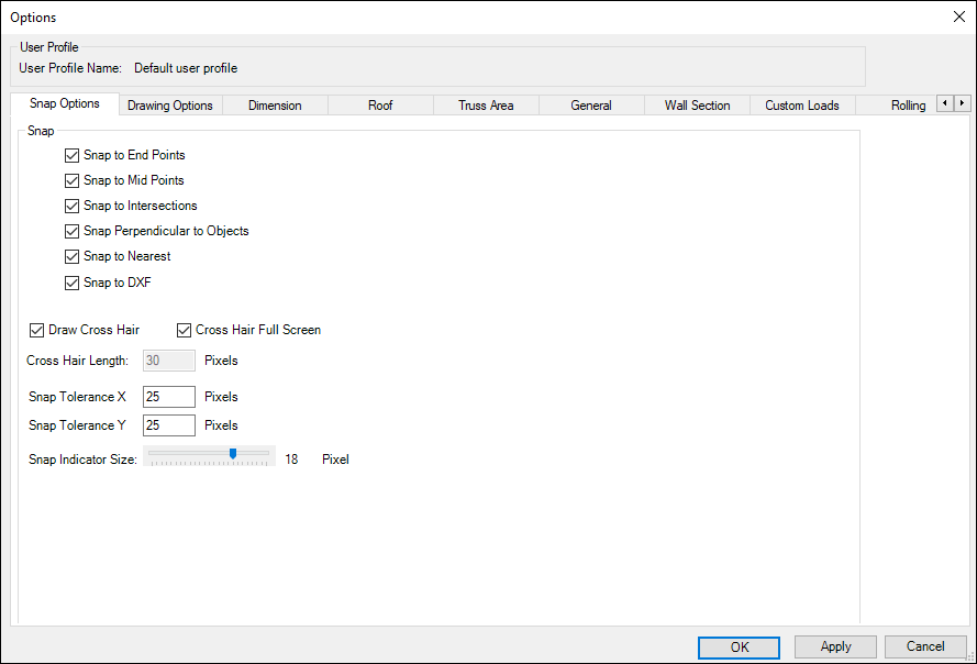
Then if we back to figure 2. The next button will be -Options-. Here the user will be able to control many orders like the following: -
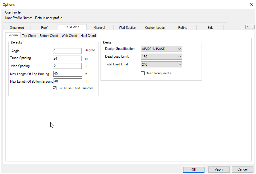
According to the figure below, this button gives us the availability to control of Truss Area as well as choose the section library-Properties- for each element in the Trusses (Top, Bottom, Heel, Web) chord. Also, we can choose the type of loading axis weak or strong and choose the appropriate design code and add loads.
Note: There is a detailed explanation of loads and design specifications next chapter.
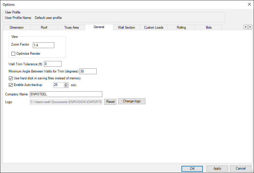
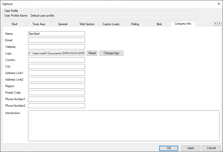
According to the figure below, this button gives us the availability to control of Rendering 3D, accuracy of lengths, autosave and company information.
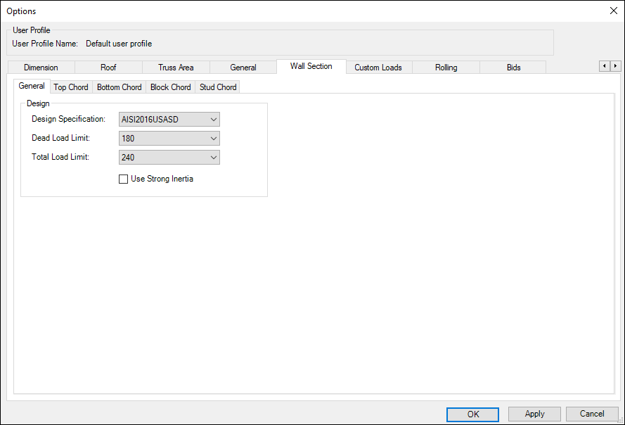
In the figure below we can choose the wall sections for each element in the wall (Top, Bottom, Block, Stud) and we can choose the type of loading axis weak or strong and choose the appropriate design code and add loads.
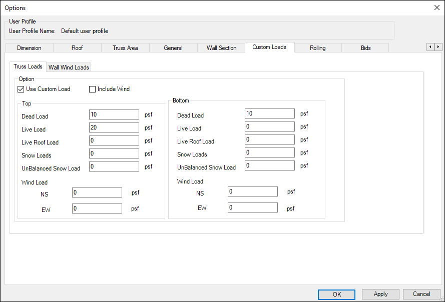
In this section, we can add loads per square foot (PSF).
Note: There is a detailed explanation of loads and design specifications next chapter.
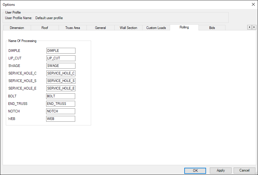
According to the figure below, this button gives us the availability to control of rolling machines names
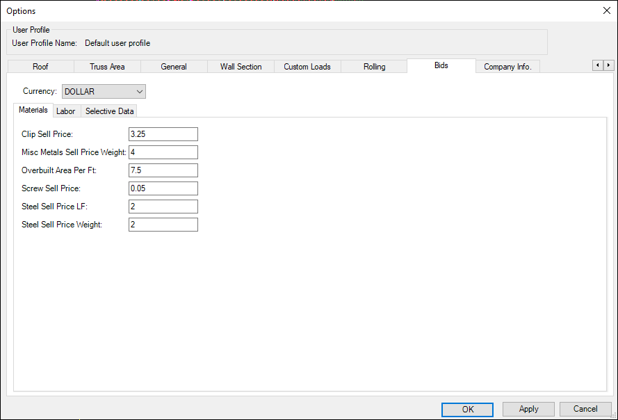
In the figure below, we can see the default prices for bids in USA as well as there is an option to change it and choose currency between the following (Turkish lira TL, US Dollar $, British pound sterling GBP, Euro €)
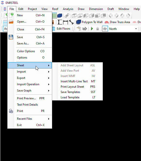
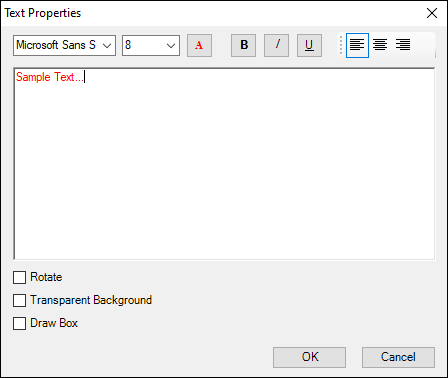
If we select insert multi-line text, we can add any text with a format as shown in the figure below
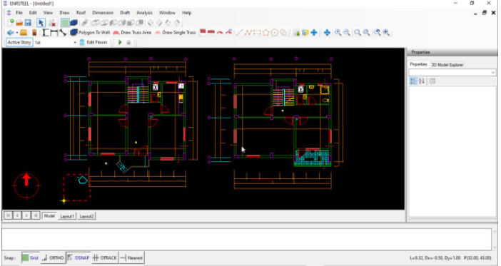
Then from the import tab, we can bring the engineering plans to the software by many ways, like DXF files from AutoCAD, image files, ITR files, or we can generate a truss or roof in AutoCAD and then import it to the software easily the examples bellow explain how these functions work.
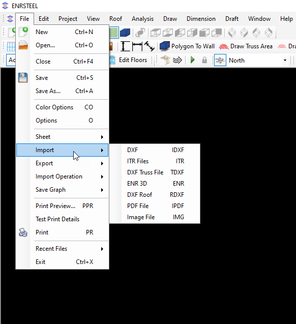
DXF
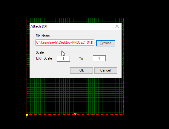
Users can attach one or more DXF files to trace floors. ENRSTEEL uses 1unit=1ft so the scale of imported drawings shall be adjusted accordingly. For example, if imported DXF has 1 unit=1 inch, then scale shall be 1 model unit (ft) = 12 imported unit (inch). Users can detach DXF files when they are no longer needed.
The following steps explain how this function work:
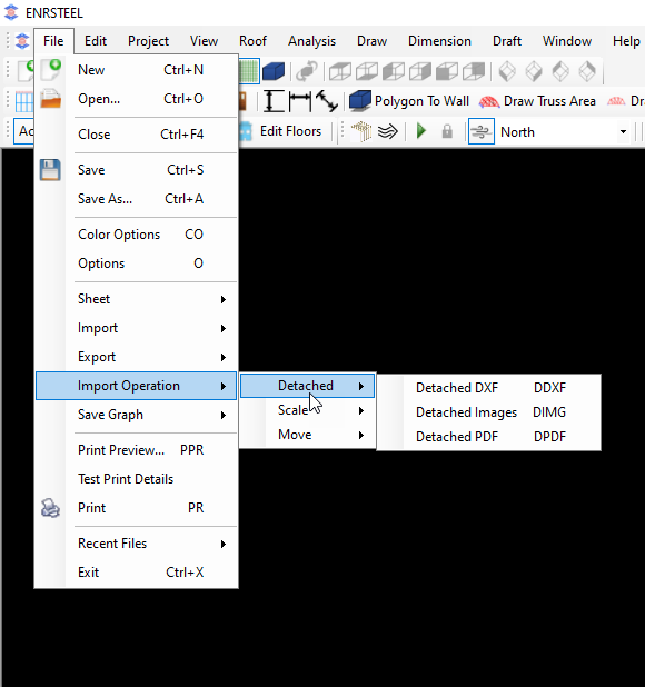
Also, if users no longer needed to DXF file then they can detach it as the following:
Click file button from menu bar then hit detach then select DXF as in figure 4,5.


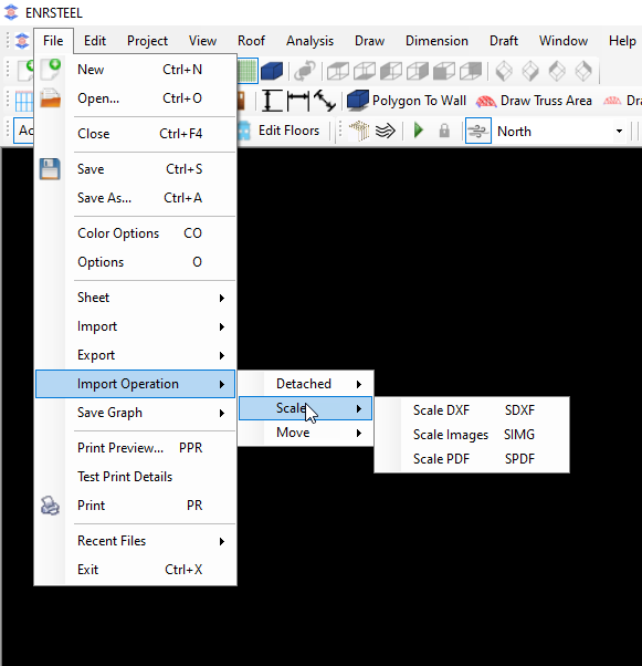
Hint: From file button from menu bar if users select import operation option they can do many processes like Detach, Scale and Move for each of DXF files, images and Pdf files as shown in figure 6,7and 8.
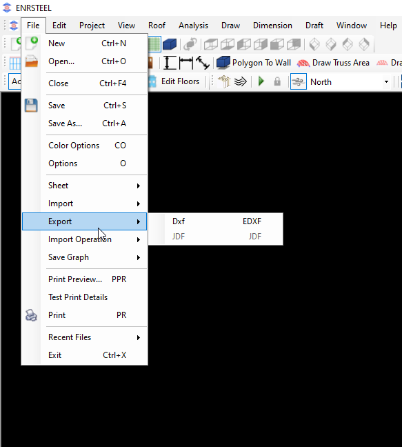
Also, they can Export the drawings which done by software to another software like Autocad for example as shown in figure 9.

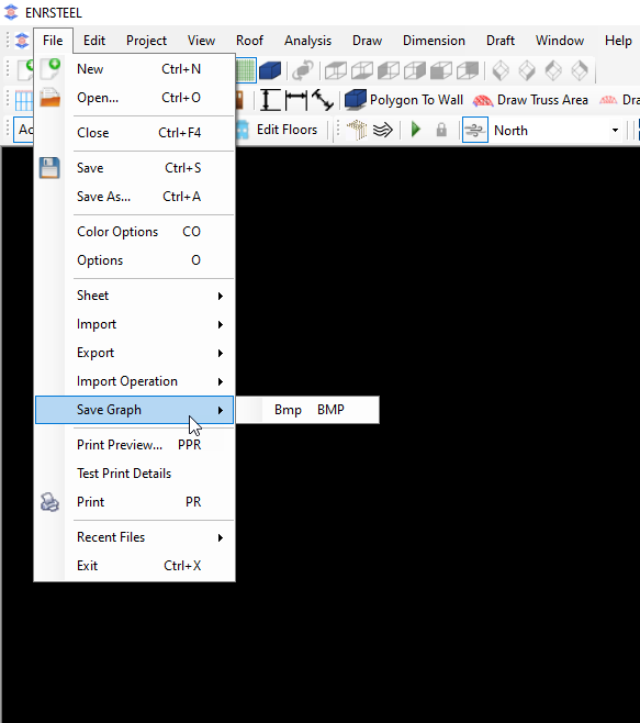
According to the figure below, this button gives us the availability to saving the current scene as BMP
Important Concepts
A few concepts and terms used in ENRSTEEL are fundamental to understand how to use it.
Level: A structural model of a multi-story building is divided into levels. Each Level consists of the wall framing for a story and the floor or roof framing above the story
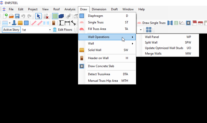
Wall: Objects represent vertically framed walls. Walls are further classified as bearing or non-bearing, also known as a partition wall. Walls are comprised of repetitive studs and unique objects such as openings with headers. Solid Walls are a special type of bearing wall that also provides existing wall or concrete wall
Roof: Represents regions of multi sloped areas. It is architectural component. It is used to get truss envelope.
Plane: Represents regions of one sloped areas. It is architectural component. It is used to get truss envelope.
Truss area: Represents regions of covered by trusses. Trusses generated according to truss area properties.
Single truss: Represents one truss. Single truss has own properties.
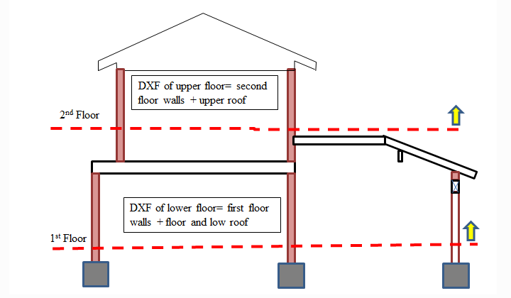
Level concept to consider in DXF data or drawing elements.
Creating and Editing Floors
Edit floors will open a form to define number of floors and default heights.
Note that ceiling heights, framing thickness and sheathing thickness should be representative of the average value of the floor but the program will allow for local variations. The calculated floor height will be used in generation of wind as well as calculating default wall weights.
The following steps show how we can add typical floors :
Note: You must set “Active Story” before drawing elements
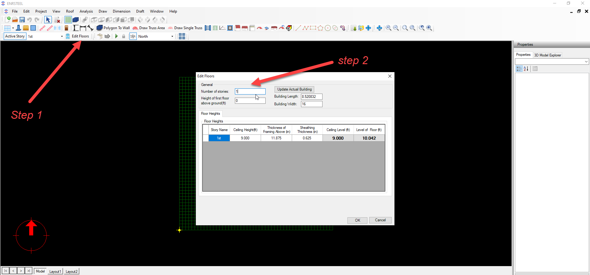
According to fig.10, we can know some information about global dimensions for building-Drawing- which we have after clicking on Update actual building button. We can know the length, width and height of the building, height of 1st floor above the ground in feet and more information as in fig.10.
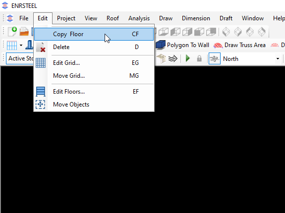
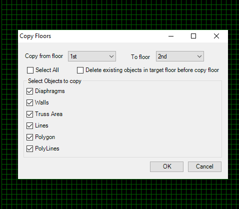
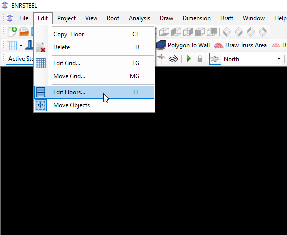
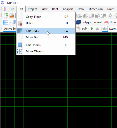
Then from Edit tab in menu bar if we select copy floor we can get the screen as in fig.11 to select the items which we need to copy to the new floor. As well as we can go to fig.10 by clicking on Edit floor button as in fig.12.
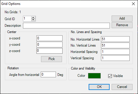
To Edit grid from edit ta on menu bar hit Edit grid then the screen as in fig.13 will show up to give us the availability to change grid as we wanted.
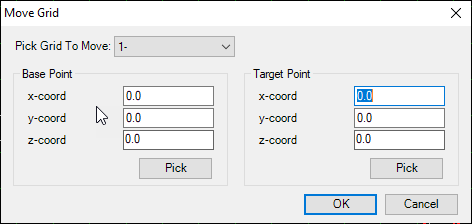
Note: each lien unit in grid represent 1 foot. Also we can add more than one grid in the working space. And we can move the grid via entering the coordinates or manually after we hit “Pick” button as in fig.14.
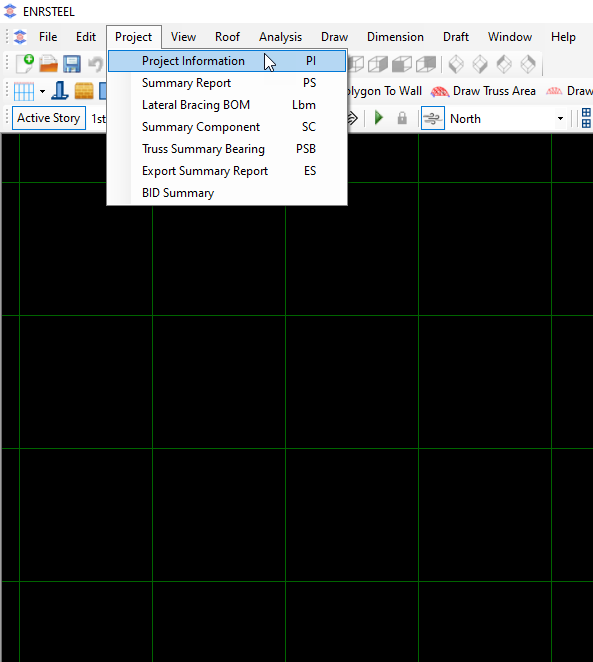
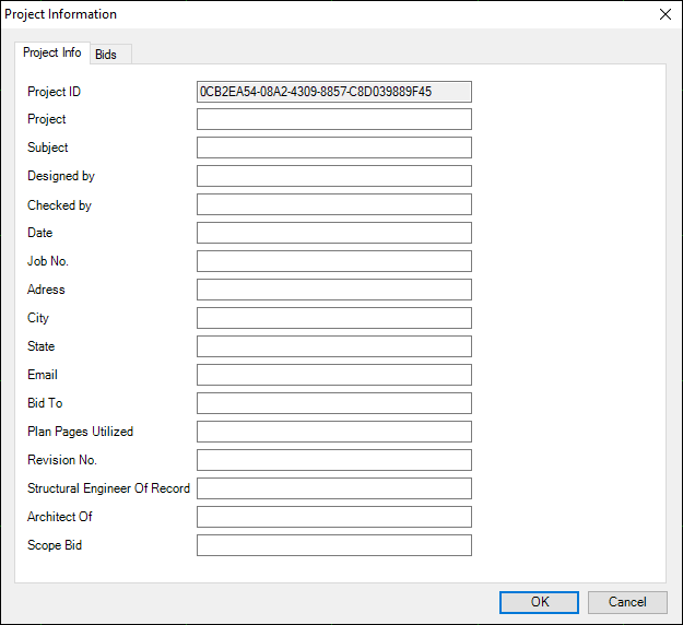
From Project tab in menu bar the users can inserts current project information see fig15, and we can see the default bid prices see fig 16. Also, we can print many reports in both PDF and excel form.
Note: To see output reports look at Reports chapter
Note: For default bid prices the users have the availability to change it also they can change the currency. The available currency is (Turkish lira TL, US Dollar $, British pound sterling GBP, Euro €).

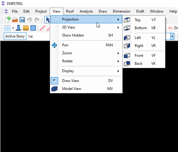
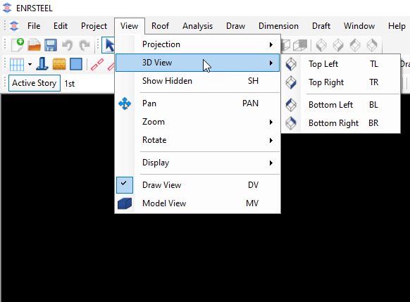
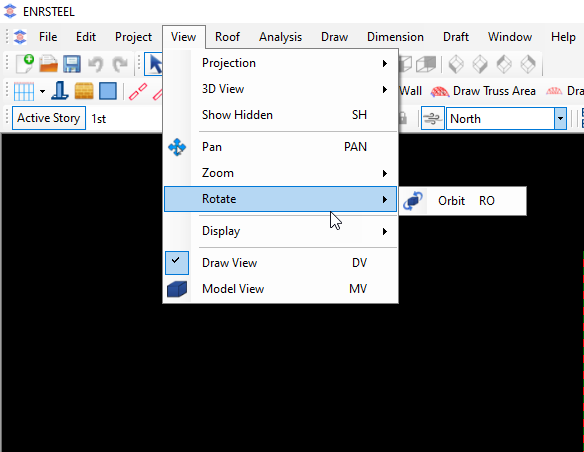
From view tab from menu bar users can see the drawings which they did in 3D from different view as shown in figures bellow see fig 17,18.
Also, they have Pan option which allows them to move drawings easily, rotate it, and zoom it in different ways see fig 19,20.
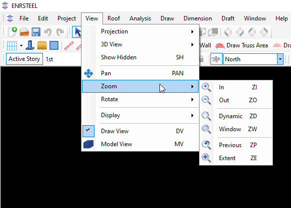
Display button allows users to show/hide any part of the work. See fig 21

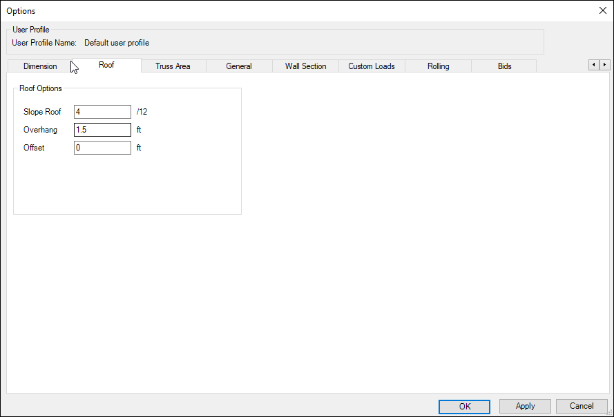
Figure 22 show us the ways to create Roofs or Ceilings.
Note: Users can see how these ways work in Drawing chapter
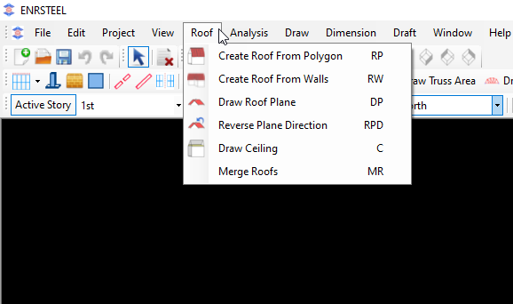
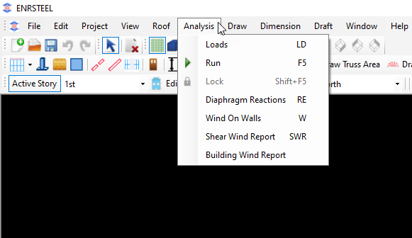
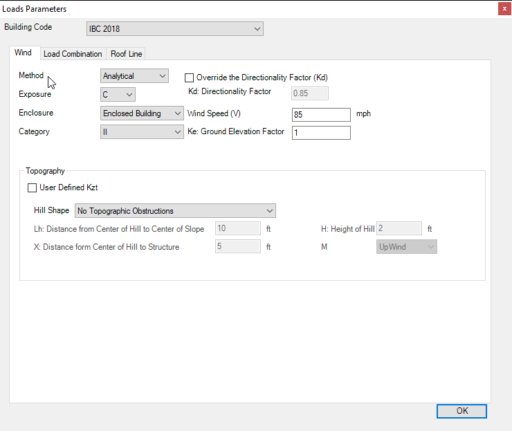
Figure 23 tell us about loads, loads combinations, wind load and reports as well as users can run the designs by clicking at run button or F5 key on keyboard.
Note: look at Loads chapter to see how we can add loads and look at Reports chapter to see the effect of loads and wind load report.
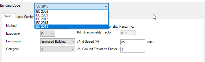
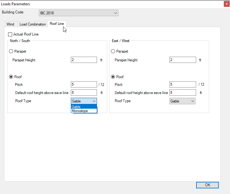
Figures 24,25,26 show users what information they can add on load sections , loads combinations, wind information, available codes and standers and roof loads.
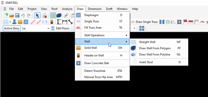
Figures 27,28 showing the elements and components which we can draw and design.
Note: look at drawing chapter to see more details about drawings.
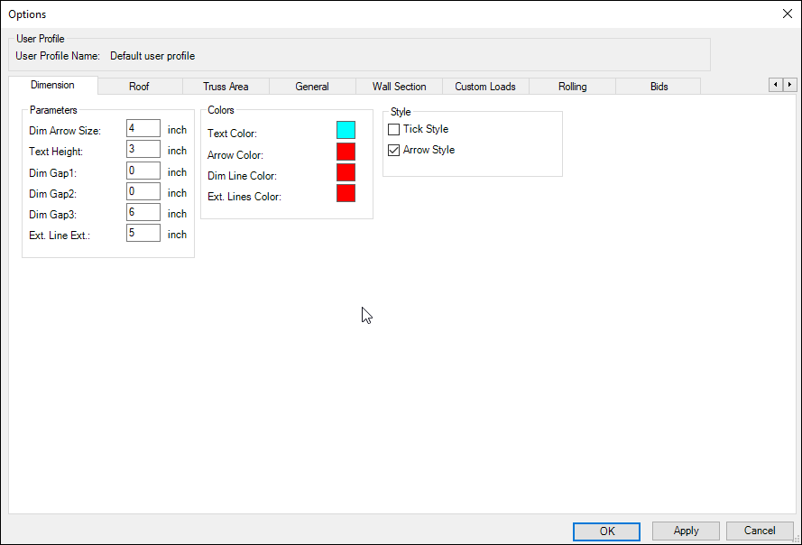
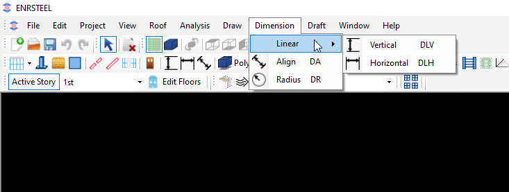
Dimension tab on menu bar has 3 ways of measurements as shown. All dimensions measured by feet and inches.
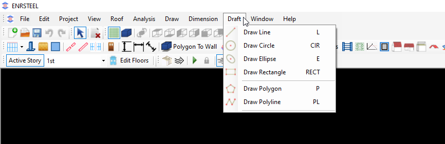
The figure below showing Draft tab in menu bar. Users can draw some shapes as shown. It’s necessary to know that we can generate walls, Trusses, Ceilings and Roofs from Polygon and the drawing chapter telling us how we can do that.
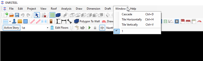
The figure below showing window tab in menu bar which allow to users to see the current open work of the software.